FOR YOUR SAFETY If you smell gas: 1. Open windows. 2. DO NOT try to light any appliance. 3. DO NOT use electrical switches. 4. DO NOT use any telephone in your building. 5. Leave the building. 6. Immediately call your local gas supplier after leaving the building. Follow the gas suppliers instructions. 7. If you cannot reach your gas supplier, call the Fire Department.
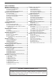
TABLE OF CONTENTS SECTION 1: Heater Safety...................................................... 2 SECTION 2: Installer Responsibility ..................................... 2 2.1 Clearances to Combustibles ........................................ 2 2.2 Corrosive Chemicals.................................................... 2 2.3 National Standards and Applicable Codes .................. 2 SECTION 3: Critical Considerations ..................................... 3 3.1 Basic Information .......................
TABLE OF FIGURES Figure 1: Condense Drain ......................................................... 3 Figure 2: Installation Clearances and Clearances to Combustibles ............................................................. 4 Figure 3: Suspension Methods ................................................. 9 Figure 4: Flue and Roof Detail ................................................ 10 Figure 5: Control Section & Upper Panel ................................ 11 Figure 6: Alternate .....................
Product Approval ROBERTS GORDON® appliances have been tested and CE certified as complying with the essential requirements of the Gas Appliance Directive, the Low Voltage Directive, the Electromagnetic Compatibility Directive and the Machinery Directive for use on natural gas and LPG when installed, commissioned and maintained in accordance with these instructions. These instructions refer to appliances designed to operate in the European Union.
DUALAIR® HEATING AND COOLING UNITS INSTALLATION OPERATION AND SERVICE MANUAL SECTION 1: HEATER SAFETY Your Safety is Important to Us! This symbol is used throughout the manual to notify you of possible fire, electrical or burn hazards. Please pay special attention when reading and following the warnings in these sections.
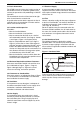
SECTION 3: CRITICAL CONSIDERATIONS SECTION 3: CRITICAL CONSIDERATIONS 3.1 Basic Information The CTUD heater that forms the heating section of ® the DualAir unit has an automatic ignition burner and may be operated as fully modulating or ON/OFF operation. The standard unit has the air flow from left to right when viewed from the controls side. A special order version with the opposite air flow is available where the combustion air intake and flue will be at the front of the unit. 3.
DUALAIR® HEATING AND COOLING UNITS INSTALLATION OPERATION AND SERVICE MANUAL WARNING Fire Hazard Some objects will catch fire or explode when placed close to heater. Keep all flammable objects, liquids and vapours the required distance away from the heater. Failure to follow these instructions can result in death, injury or property damage.
SECTION 4: SPECIFICATIONS SECTION 4: SPECIFICATIONS 4.
DUALAIR® HEATING AND COOLING UNITS INSTALLATION OPERATION AND SERVICE MANUAL 4.2 General Technical Data Table Model Fan Data Designed Air Flow # with Clean Filters Min Air Flow at Coil Max Air Flow at Coil Fan Unit Fan Pulley Motor Pulley Vee Belts m3/sec m3/sec m3/sec mm PCD mm PCD 75 90 115 100 2.88 3.7 1.66 2.60 3.71 5.34 457-486 Double Inlet Belt Drive 2A x 180 / 2A x 200 2A x 180 2A x 100 / 2A x 95 2A x 112 / 2A x 118 2 x A 63 2 x A 64 Electrical Data - All models need 400v 50Hz 3N supply.
SECTION 4: SPECIFICATIONS 4.3 Technical Data Table - Heater Section Appliance Category II 2H/L 3B/P Heat Input Gross Calorific Value Heat Input Net Calorific Value Model kW Btu/h x 1000 kW 75 95 324 86 90 111 379 100 100 119 406 107 115 134 457 121 Btu/h x 1000 Approximate kW 293 78 341 91 365 98 413 111 Max Heat Output Min Heat Input - Low Fire Gross Calorific Value Min Heat Input - Low Fire Net Calorific Value Btu/h x 1000 kW 266 66.5 311 77.7 334 83.3 379 93.8 Btu/h x 1000 kW 227 60.
DUALAIR® HEATING AND COOLING UNITS INSTALLATION OPERATION AND SERVICE MANUAL ® 4.4 DualAir Performance Data - Graph of Air Flows v Static Pressure 4.4.1 DAT75 and 90 (2.2 kW or 4 kW motor) 400 Static Pressure Pa 350 300 250 200 150 100 50 0 2.2 2.4 Air Flow m3/sec 2.6 2.8 3.0 95 mm motor pulley x 180 mm fan pulley 100 mm motor pulley x 200 mm fan pulley 3.2 3.4 3.8 4.0 4.4.2 DAT100 and 115 (4 kW motor) 400 Static Pressure Pa 350 300 250 200 150 100 50 0 2.8 3.0 Air Flow m3/sec 118 mm Pulley 8 3.
SECTION 5: HEATER INSTALLATION SECTION 5: HEATER INSTALLATION 5.1 General ® DualAir units are designed for installation above 2.5 m. When connected to duct delivery systems any suitable location will be acceptable. ® For floor mounting, the DualAir unit may stand directly on its base. 5.2 Handling All DualAir® units have steel channel sections at the base to be used to support the equipment. Three steel sections are also provided across the top of the ® unit for support.
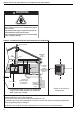
DUALAIR® HEATING AND COOLING UNITS INSTALLATION OPERATION AND SERVICE MANUAL SECTION 6: FLUE INSTALLATION 6.1 Flue Installation WARNING Figure 4: Flue and Roof Detail Flue Terminal Fire Hazard Masterflash soaker flashing or Rain Collar. Some objects will catch fire or explode when placed close to the heater section. Keep all flammable objects, liquids and vapours the required distance away from the heater section. Failure to follow these instructions can result in death, injury or property damage.
SECTION 6: FLUE INSTALLATION 5. Refit the air intake spigot to the flexible hose reusing the hose clamp and to the upper panel using the original screws. 6. Align the flues’ inner and outer spigots and attach through the holes in the upper panel reusing the original screws. 7. Refit the lower door.
DUALAIR® HEATING AND COOLING UNITS INSTALLATION OPERATION AND SERVICE MANUAL Figure 7: Vertical and Horizontal Flue Termination - Type B22 Appliance Roof Terminal Masterflash Metal Sleeve (25 mm air gap to combustible material) Fold leg down Fold foot out Flue Air Intake Terminal Cover Figure 8: Vertical and Horizontal Flue Termination - Type C12 C32 & C62 Appliances Roof Terminal Masterflash Manifold Air Intake 12 Flue
SECTION 7: AIR SUPPLY SECTION 7: AIR SUPPLY 7.1 Room Sealed Installation When installed as a room sealed heater, the air for combustion is drawn in from outside the building. It is important to ensure that there is adequate ventilation to provide air for the distribution fan/s. 7.2 Open Flued Installation Ensure adequate air supply at all times for both combustion and heating requirements in accordance with local and national codes.
DUALAIR® HEATING AND COOLING UNITS INSTALLATION OPERATION AND SERVICE MANUAL SECTION 8: OPTIONAL HEATER CONFIGURATIONS 8.1 Distribution Duct ® The duct must be designed as described on Page DualAir units are designed to be connected to 14, Section 8.1 and Figure 10 to ensure that there is distribution and air inlet ducting. It is recommended that flexible duct connectors and/ a homogenous air flow across the whole heat or attenuators are used to reduce duct born noises. exchanger.
SECTION 9: GAS PIPING SECTION 9: GAS PIPING 9.1 Connections Connect the heater to the gas supply ensuring that the final connections are as follows: • The gas supply pipe is adequately sized to carry the total volume of gas for the complete installation. • An isolating valve and union connection should be used and fitted into the supply adjacent to the heater. • For suspended heaters, use an approved metal flexible connection between the isolating valve and the heater.
DUALAIR® HEATING AND COOLING UNITS INSTALLATION OPERATION AND SERVICE MANUAL SECTION 10: WIRING AND ELECTRICAL INFORMATION cooling temperature control. See Page 20, Section 10.1 Electrical Supply All heater models need a constant 400 V 50 Hz 3 ø 10.6. To operate the modulating gas burner, a further supply connected to terminals L1,L2, L3, N & Earth. input of 0-10 V DC is required with 0V giving Polarity "L1 & N" must be correct.
SECTION 10: WIRING AND ELECTRICAL INFORMATION 10.
DUALAIR® HEATING AND COOLING UNITS INSTALLATION OPERATION AND SERVICE MANUAL 10.
SECTION 10: WIRING AND ELECTRICAL INFORMATION 10.
DUALAIR® HEATING AND COOLING UNITS INSTALLATION OPERATION AND SERVICE MANUAL 10.
SECTION 11: COMMISSIONING SECTION 11: COMMISSIONING Gas Fired Heater Installation, service, commissioning and annual inspection of the heater must be done by a contractor qualified in the installation and service of gas-fired heating equipment. Read this manual carefully before installation, commissioning, operation, or service of this equipment. All components are accessed via the hinged door. Opening the door exposes live electrical connections and hot components.
DUALAIR® HEATING AND COOLING UNITS INSTALLATION OPERATION AND SERVICE MANUAL Figure 12: Automatic Burner Control Box Sequence Burner sequence for Honeywell S4563 or S4565C START RUN CLOSE DOWN Supply 230 V Flue Fan 30 Sec. Purge* Pressure Switch P NO C NC ts** Ignition Spark Start Gas Valve Flame Signal Required Incoming Signals Signals Output By Control *Purge time begins at pressure switch change over.
SECTION 11: COMMISSIONING sure must be corrected before completing the commission. All DualAir units are fitted with fully modulating burner operation. The Honeywell automatic gas 2. Release the moving shaft and observe that the valves are fitted with the Honeywell Modureg burner pressure returns to the minimum setting. modulating regulator. 3. Turn off the external controls and reconnect the See Page 22, Figure 13. electrical leads to the Modureg regulator.
DUALAIR® HEATING AND COOLING UNITS INSTALLATION OPERATION AND SERVICE MANUAL water collection and a shortened heat exchanger life. Pressure Switch The pressure switch is factory pre-set for each model and is not adjustable. ® 11.6 Turning Off the DualAir Unit Set the external controls to the off position and the main burner will stop. The fans will run until they are stopped automatically by the fan thermostat. Do not use electrical isolator for control of heater.
SECTION 12: USER INSTRUCTIONS SECTION 12: USER INSTRUCTIONS 12.1 User Instructions 12.3 Common User Controls 12.3.1 Combination Fan/Limit Thermostat The DualAir units are fully automatic and operate from the external controls fitted on site. The Combination Fan/Limit Thermostat is located inside the access door at the top of the heater. See The only user controls at the heater are the: Page 38, Section 16.3. Burner lockout reset button: ...................................See Page 26, Section 12.3.
DUALAIR® HEATING AND COOLING UNITS INSTALLATION OPERATION AND SERVICE MANUAL ® Do not operate the DualAir unit without filters as the cooling coil may become blocked and impossible to clean. WARNING Explosion Hazard If control locks out, do not make more than 3 attempts to restart the heater. Dangerous gas mixtures can build up. The fault must be traced and repaired by a registered installer or service engineer. Failure to follow these instructions can result in death, injury or property damage. 12.3.
SECTION 12: USER INSTRUCTIONS FOR YOUR SAFETY If you smell gas: 1. Open windows. 2. DO NOT try to light any appliance. 3. DO NOT use electrical switches. 4. DO NOT use any telephone in your building. 5. Leave the building. 6. Immediately call your local gas supplier after leaving the building. Follow the gas suppliers instructions. 7. If you cannot reach your gas supplier, call the Fire Department.
DUALAIR® HEATING AND COOLING UNITS INSTALLATION OPERATION AND SERVICE MANUAL SECTION 13: SERVICING 13.1 Servicing Instructions ® After commissioning, the DualAir unit will require maintenance to be carried out annually. If the ® DualAir unit is used in a dirty or dusty area, more frequent maintenance may be necessary. Installation, service and annual inspection of heater must be done by a contractor qualified in the installation and service of gas-fired heating equipment.
SECTION 13: SERVICING 13.5 Gas Control Valve Maintenance No regular maintenance is required on these devices. To change gas control valves, See Page 36, Step 16.1 and Page 40, Section 16.5. Do not repair or disassemble on site. Replace faulty gas valves with genuine ® ROBERTS GORDON replacement parts. 13.6 Flue Fan The flue fan should not require maintenance. However, If the air pressure switch is causing burner lockout then remove the flue fan from the vent box. See Page 39, Section 16.4.
DUALAIR® HEATING AND COOLING UNITS INSTALLATION OPERATION AND SERVICE MANUAL SECTION 14: CONVERSION BETWEEN GASES 14.1 General Conversion between gasses will require a change of burner injectors and the gas valve re-commissioning to the new conditions. 14.2 Burner Conversion Conversion of the burner assembly from one gas to the other is the same for all types of heaters. 1. Remove the burner compartment cover as shown on Page 37, Section 16.2. 2.
SECTION 15: TROUBLESHOOTING SECTION 15: TROUBLESHOOTING 15.1 General WARNING Explosion Hazard Installation must be done by a registered installer/ contractor qualified in the installation and service of gas-fired heating equipment or your gas supplier. Failure to follow these instructions can result in death, injury or property damage. Start Are gas & electrical supplies on? No Turn on supplies. Yes Use 15.2 to test burner.
DUALAIR® HEATING AND COOLING UNITS INSTALLATION OPERATION AND SERVICE MANUAL 15.2 Troubleshooting For Automatic Ignition Burner Systems There are two burner controls used. Honeywell S4563C and S4565C. They both have similar operating sequences. To measure flame current, connect a 0 - 50 μA DC meter in series with the flame probe. If the meter reads negative values, then reverse the test leads. WARNING Electrical Shock Hazard Do not touch ignition components.
SECTION 15: TROUBLESHOOTING 15.3 Troubleshooting for Flame Supervision System START Connect a DC ammeter in series with the flame probe. Is the green light on and at least 1 µA DC fame current? No Use section 15.1 to trace the fault. Yes Is there a current flowing in the flame probe circuit with no flame present? Is the connecting lead damaged? Is the flame probe Yes damaged or touching earthed components? Yes Repair or replace as necessary. Yes Control box faulty. Replace with correct type.
DUALAIR® HEATING AND COOLING UNITS INSTALLATION OPERATION AND SERVICE MANUAL 15.4 Troubleshooting for Solenoid Valves START Is 230v at the valve terminals at the appropriate time. No Fault elsewhere No Fault elsewhere No Valve faulty. Replace with one of correct type. No Valve faulty. Replace with one of correct type. No If problems persist, contact ROBERTS GORDON® at Tel: +44(0) 190 249 8733 or www.rg-inc.com Yes Is gas pressure at inlet of the valve correct for gas type? Note pressure found.
SECTION 15: TROUBLESHOOTING 15.6 Troubleshooting for Fan Contactor START Does main fan run automatically in heating mode? No Is power supply 400v at three phase and N at the main terminal? No Wiring faulty or faulty combination thermostat. Investigate. Fault elsewhere No Yes Does fan run when white No button of combination thermostat is pushed in? Is there 230v at contactor coil terminal A1 and A2? No Is there 230v between Press in overload reset No terminals 96 and A1 on No button and retest.
DUALAIR® HEATING AND COOLING UNITS INSTALLATION OPERATION AND SERVICE MANUAL SECTION 16: REMOVAL AND REPLACEMENT PARTS Figure 17: Standard Regulator Removal See warnings and notes on Page 28, Section 13 Sealing before removing or replacing parts. Washer Burner Components All serviceable burner parts are accessed by the door on the side of the heater. See Page 5, Section 4. 16.1 Gas Valve The VR4605 gas valve is fitted with the V7335A Modureg regulator (P/N L512) supplied as a separate component.
SECTION 16: REMOVAL AND REPLACEMENT PARTS 16.2 Burner Compartment The burner compartment is a sealed Burner compartment. Following any work, compartment re-seal the compartment with the gas cover pipe rubber seal fully in place and all Flame probe screws fitted and tight. Viewing port for flame probe Remove flexible air duct from spigot Ignition electrode Viewing port for ignition electrode Remove access plate Rubber Seal Remove screws and pull off burner cover 16.2.
DUALAIR® HEATING AND COOLING UNITS INSTALLATION OPERATION AND SERVICE MANUAL 16.3 Ignition Electrode and Flame Probe. Fan/Limit Thermostat Burners Secondary Limit Thermostat Flame Probe Remove all burner compartment screws to remove the burner compartment and access the Front View. Flame Probe Remove Screw Burner Compartment Front Views Ignition Electrode Ignition Electrode (3 mm) .120" spark gap Burners To replace the ignition electrode or flame probe, remove the electrical lead and screw.
SECTION 16: REMOVAL AND REPLACEMENT PARTS 16.4 Flue Fan Rear Panel Hole Remove screws securing outlet flange to the flue adapter. Flue Adapter to Flue Fan screws Vent Box Vent Box screws Outlet Gasket Flue Adapter Flue Fan Disconnect electrical connections at plug in tabs.
DUALAIR® HEATING AND COOLING UNITS INSTALLATION OPERATION AND SERVICE MANUAL 16.5 Heater Pressure Switch Pull off 3 way connector. Spring open plastic clips of mounting cradle. Replace with correct type of pressure switch for model. The pressure switches are colour coded for each pressure setting. WARNING Carry out a commission after working on or changing a pressure switch. See Page 21, Section 11. Carbon Monoxide Hazard Use correct pressure switch specified for each model.
SECTION 16: REMOVAL AND REPLACEMENT PARTS 16.6 Cooling Coil Safety Devices 16.6.1 Cooling Coil Frost Thermostat The sensing element for this device is inserted into the pocket of the cooling coil situated through the access hole in the coil cover. The frost thermostat has two settings marked as set point with an arrow head and "diff". The control should be set at 5° C with a 1° C differential. To replace, remove screw and pull off knob. Remove cover. Disconnect wires.
DUALAIR® HEATING AND COOLING UNITS INSTALLATION OPERATION AND SERVICE MANUAL 16.7 Ignition Control IT IS IMPORTANT THAT ONLY THE CORRECT IGNITION CONTROL SPECIFIED FOR EACH MODEL TYPE IS USED WHEN REPLACING THESE ITEMS. 16.7.1 S4563C This control is mounted at the electrical mounting plate. Pull out the 3 cable connectors. Pull out ignition cable, ignition earth and flame probe cable noting their positions. Remove the screws. Refit in reverse. Ensure correct location of ignition and flame probe cables. 16.
SECTION 16: REMOVAL AND REPLACEMENT PARTS 16.8.1 Fan Removal and Replacement Fan Plate Fan Outlet Flange Securing Screws Fan Mounting Brackets (re-use on new fan) Bracket Screws (re-use on new fan) Fan Foot Screws Description Torin Fan DDC 270-270 Torin Fan DDC 241-241 Part Number A047 A049 1. Remove motor leaving the pulley in place. See Page 42, Section 16.8. 2. Remove screws securing the fan outlet flange to the fan panel. (captive nuts) 3.
DUALAIR® HEATING AND COOLING UNITS INSTALLATION OPERATION AND SERVICE MANUAL Figure 19: Combination Fan/Limit Thermostat WARNING Fire Hazard Break-off link must be removed from replacement thermostat. Heat exchanger damage may result. Failure to follow these instructions can result in death, injury, property damage or product damage. Dial Set Point 3 Limit Temp.
Attach this information to the wall near the ROBERTS GORDON® heater. ® Read the installation, Commissioning, Operation and Service Manual thoroughly before installation, operation or service. WARNING OPERATING INSTRUCTIONS 1. STOP! Read all safety instructions on this information sheet. 2. Open the manual gas valve in the heater supply line. 3. Turn on electric power to the heater. 4. Set the thermostat to desired setting (above ambient temperature). The automatic starting sequence begins.