ROBERTS GORDON ® BZC 100 CONTROLLER Installation Manual WARNING Improper installation, adjustment, alteration, service or maintenance can result in death, injury or property damage. Read the installation and operation manuals thoroughly before installing or servicing this equipment. Installation must be done by a electrician qualified in the installation and service of control systems for heating equipment.
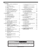
TABLE OF CONTENTS 1. Introduction 1.1 What is a ROBERTS GORDON® BZC Controller? . . . . . . . . . . . . . . . . . . . . . . . . .1 1.2 General Requirements . . . . . . . . . . . . . . . .1 1.3 Check Installation Materials . . . . . . . . . . . .1 1.4 Safety . . . . . . . . . . . . . . . . . . . . . . . . . . . .1 1.5 Example Site Layout . . . . . . . . . . . . . . . . .2 1.6 Internal Connection Information . . . . . . . . .3 1.7 How to Read the Configuration Sheet . . . .4 1.
TABLE OF FIGURES Figure 1 Example Site Layout Drawing . . . . . . . . . . . . . .2 Figure 2 Internal Connection Diagram . . . . . . . . . . . . . .3 Figure 3 Example Configuration Table . . . . . . . . . . . . . .4 Figure 4 Example External Wiring Diagram . . . . . . . . . .5 Figure 5 Keypad Layout . . . . . . . . . . . . . . . . . . . . . . . . .7 Figure 6 ROBERTS GORDON® BZC 100 Cover Detail . .8 Figure 7 Mounting Hole Layout . . . . . . . . . . . . . . . . . . . .
SECTION 1: INTRODUCTION SECTION 1: INTRODUCTION 1.1 1.3.3 WHAT IS A ROBERTS GORDON BZC CONTROLLER? The ROBERTS GORDON® BZC 100 is a micro processor based controller designed for the most efficient control of CORAYVAC®, VANTAGE®, GORDONRAY® and CARIBE® heaters. This controller is capable of giving control outputs from 3 relays, 1 of which affords heating zone control capabilities. The controller also features 2 inputs which are used for signal condition monitoring. 1.
ROBERTS GORDON® BZC 100 INSTALLATION MANUAL IMPORTANT READ THIS FIRST!!!! 1.5 EXAMPLE SITE LAYOUT It is essential to follow this section to understand how to use the information in this manual. Please ensure that you understand this example before proceeding with the installation. CORAYVAC® system arranged in a single zone. Shown below is an example layout for a building where a ROBERTS GORDON® BZC 100 Controller will be used to control the infrared heating system shown.
SECTION 1: INTRODUCTION 1.6 INTERNAL CONNECTION INFORMATION The following Section shows the configuration of relays and inputs for the example layout shown on Page 2, Section 1.5, Figure 1. Below is a diagram showing the terminal layout within the controller. The relay contacts and inputs are assigned functions through the configuration process. The controller needs to be configured for the individual application.
ROBERTS GORDON® BZC 100 INSTALLATION MANUAL 1.7 HOW TO READ THE CONFIGURATION SHEET nal relays. The tables shown on Page 4, Section 1.7, Figure 3 represent the assignments of relays and inputs that would result from the configuration of the panel for the example site layout shown on Page 2, Section 1.5, Figure 1. In the example, the CORAYVAC® zone requires one output for the burners and one for the pump. The pump assigned to Zone 1 is connected via a load relay to RL2 (see Page 5, Section 1.
SECTION 1: INTRODUCTION 1.8 EXAMPLE LAYOUT WIRING INFORMATION The external wiring diagram shown below represents the external wiring required for the example site layout on Page 2, Section 1.5, Figure 1. The information on the configuration tables for outputs and inputs determines the connection required. The product specific wiring arrangements are found starting on Page 12, Section 4. For the external wiring shown below, see the typical CRV zone wiring diagram, Page 17, Section 4.6.
ROBERTS GORDON® BZC 100 INSTALLATION MANUAL ROBERTS GORDON® BZC 100 CONFIGURATION Controller Serial Number __________________ Project Name: __________________________ Roberts-Gordon Layout Drawing Number ______ Configured By: __________________________ Date: __________________________________ RL1 1 RL2 2 SECTION NO. PRODUCT PUMP NO. INPUT SECTION NO. RELAY Y/N TABLE OF INPUTS PRODUCT PUMP NO. OUTPUT ZONE NO. TABLE OF OUTPUTS ZONE NO. 1.9 RL3 1.9.
SECTION 2: SPECIFICATIONS 2 3 1 4 5 6 7 8 9 FIGURE 5 - Keypad Layout SECTION 2: SPECIFICATIONS 2.1 Protection: ABS (UL 94-5VA Rated) 3.5 lbs (1.6 Kg) 7.8" x 2.4" x 11.4" 199 x 62 x 290mm Rating IP20 2.5 Supply: Relay Outputs: 2.3 PUMP STARTER SPECIFICATION Full load current 1ph 3ph EP 100 Pump 1/3HP 4.8A N/A EP 201 Pump 3/4HP 6.6A N/A EP 203 Pump 3/4HP N/A 3.0A EP 301 Pump 1-1/2HP 16.0A N/A EP 303 Pump 1-1/2HP N/A 4.
ROBERTS GORDON® BZC 100 INSTALLATION MANUAL SECTION 3: INSTALLATION Installation of the ROBERTS GORDON® BZC 100 Controller and the associated external electrical wiring must be done by an electrician qualified in the installation of control systems for heating equipment. 3.1 3.2.3 Disconnect the ribbon cable from the controller PCB board. Place the cover and the hardware in a safe place for refitting after the external wiring connections have been made. 3.2.4 Position the controller.
SECTION 3: INSTALLATION Three separator plates must be removed so that one plate remains, separating low and line voltage. 3.3 ELECTRICAL INSTALLATION REQUIREMENTS WARNING Page 9, Section 3.2.10, Figure 9, shows the separator plate detail for an installation where relay 1 switches line voltage and relay 2 switches low voltage 12V DC. The three un-used separator plates must be discarded.
ROBERTS GORDON® BZC 100 INSTALLATION MANUAL 3.3.2 ROBERTS GORDON® Pump Requirements The pumps must be isolated separately from the panel. The contactor or relay will be energized via an output from the panel switched through the designated relay. See Page 6, Section 1.9 for site specific configuration. Use the table below to select the correct pump external wiring diagram. ROBERTS GORDON® Pump EP 100 Supply Voltage Relay Coil Page Section 120V 1ph 120V AC 16 4.5 EP 201 120V 1ph 120V AC 16 4.
SECTION 3: INSTALLATION 3.3.5 Cable requirements: Line power supply: As per individual building specification for class of cable to be used. Use copper conductors only. To size the cable, use the amperage of the burners given on Page 9, Section 3.3.1, for each individual zone. 3.3.6. Sensor Mounting The sensor measures the air temperature in the building. It is important that the sensor is located in an area within the heated zone at occupant level.
ROBERTS GORDON® BZC 100 INSTALLATION MANUAL SECTION 4: TYPICAL EXTERNAL DIAGRAMS 4.
SECTION 4: TYPICAL EXTERNAL DIAGRAMS 4.2 VANTAGE® II AND VANTAGE® HE UNITARY HEATERS ARRANGED IN ONE ZONE Zone connection detail Burner 2 The power supply for each Zone must be separate from the controller supply Zone 1 Burner 1 120 V 1 ph 60 Hz Burner 2 Never directly connect the controller relay terminals to the Burners.
ROBERTS GORDON® BZC 100 INSTALLATION MANUAL 4.3 UNITARY HEATERS ARRANGED IN ONE ZONE WITH CONTROL VIA A 12V DC RELAY Zone Connection Detail Burner 2 The power supply for each Zone must be separate from the controller supply Burner 1 Zone 1 Burner 2 120 V 1 ph 60 Hz Never directly connect the controller relay terminals to the Burners.
SECTION 4: TYPICAL EXTERNAL DIAGRAMS 4.
ROBERTS GORDON® BZC 100 INSTALLATION MANUAL 4.5 VANTAGE® EV SYSTEM ARRANGED IN ONE ZONE EP100 or EP201 pump connection detail Pump 120V 1Ph 60Hz All burners must be connected to Ground (Not shown) Never directly connect the controller relay terminals to the pump motor. Zone 1 Burner 4 CR Neutral 120V Live 120V Individual supply from relay 5 for pump rated for total full load current (SeePage 7, Section 2.
SECTION 4: TYPICAL EXTERNAL DIAGRAMS 4.6 CORAYVAC® SYSTEM ARRANGED IN ONE ZONE 1 ph pump connection detail Pump 120V 1Ph 60Hz Never directly connect the controller relay terminals to the pump motor. All burners must be connected to Ground (Not shown) Zone 1 CRV Burner 4 The power supply for each pump must be separate from the controller supply. CR Load relay Neutral 120V Live 120V Individual supply from relay 2 for pump rated for total full load current (See Page 7,Section 2.
ROBERTS GORDON® BZC 100 INSTALLATION MANUAL 4.7 EP 100 AND EP 201 1PH PUMP CONNECTION (12V DC COIL) Zone 1 Pump 120V 1ph 60Hz Burner 3 All burners must be connected to the Ground (not shown) CR N Load relay L Individual supply for pump rated for total full load current (see Page 7, Section 2.3 for details) Sensor wire and input wire must be shielded cable Belden 8451 or equivalent Zone 1 Sensor + -S Burner 4 Never directly connect the controller relay terminals to the pump motor.
SECTION 4: TYPICAL EXTERNAL DIAGRAMS 4.8 EP 301 1PH PUMP CONNECTION (120V AC COIL) Pump Never directly connect the controller relay terminals to the pump motor.
ROBERTS GORDON® BZC 100 INSTALLATION MANUAL 4.9 EP 301 1PH PUMP CONNECTION ALTERNATIVE (12V DC COIL) Pump Never directly connect the controller relay terminals to the pump motor.
SECTION 4: TYPICAL EXTERNAL DIAGRAMS 4.10 EP 203 AND EP 303 3PH PUMP CONNECTION (120V AC COIL) Pump Never directly connect the controller relay terminals to the pump motor.
ROBERTS GORDON® BZC 100 INSTALLATION MANUAL 4.11 EP 203 AND EP 303 3PH PUMP CONNECTION ALTERNATIVE (12V DC COIL) Pump Never directly connect the controller relay terminals to the pump motor.
SECTION 4: TYPICAL EXTERNAL DIAGRAMS 4.12 OUTSIDE AIR BLOWER WITH 1PH PUMP CONNECTION Outside Air Blower Zone 1 Pump 1 For EP 100 or EP 201 pump connection detail refer to Page 17, Figure 18.
ROBERTS GORDON® BZC 100 INSTALLATION MANUAL 4.13 OUTSIDE AIR BLOWER WITH 1PH PUMP CONNECTION ALTERNATIVE (12V DC COIL) Outside Air Blower Pump The power supply for each pump must be separate from the controller supply For EP 100 or EP 201 pump connection detail refer to Page 17, Figure 18. For EP 301 pump connection detail refer to Page 19, Figure 20. Zone 1 Burner 4 Never directly connect the controller relay terminals to the pump motor.
SECTION 5: ALARM SIGNAL CONDITION MONITORING SECTION 5: ALARM SIGNAL CONDITION MONITORING use of input 1. Input 1 is optionally available for lockout indication or for fire safety override. Input 2 is reserved for remote time enable. Alarm signal condition monitoring capabilities are available as inputs to the controller. The number of signals available is limited to the 2 inputs available CORAYVAC® pump pressure switch reserves the 5.
ROBERTS GORDON® BZC 100 INSTALLATION MANUAL 1PH PUMP TRIP INDICATION FOR VANTAGE® EV SYSTEMS 5.2 Pump Never directly connect the controller relay terminals to the pump motor.
SECTION 5: ALARM SIGNAL CONDITION MONITORING 5.
ROBERTS GORDON® BZC 100 INSTALLATION MANUAL 5.4 BUILDING MANAGEMENT SYSTEMS REMOTE TIME ENABLE BMS Time Enable Contacts NO C NC Input wire must be shielded cable Belden 8541 or equivalent - S + 2 1 S RS485 SENSOR INPUTS + 2 1 C + - INPUTS 12 V DC 12V DC OUTPUT 3 RELAY C 2 RELAY C 1 E L L RELAY ROBERTS GORDON ® BZC 100 NEUTRALS NOTE: TYPICAL LAYOUT DRAWINGS TO BE USED IN CONJUNCTION WITH FACTORY CONFIGURATION SETTINGS - PAGE 6, SECTION 1.
SECTION 5: ALARM SIGNAL CONDITION MONITORING 5.5 FIRE SAFETY SHUT OFF FACILITY Fire Alarm System Alarm On Contacts NO C NC Input wire must be shielded cable Belden 8541 or equivalent - S + 2 1 S RS485 SENSOR INPUTS + 2 1 + - INPUTS 12 V DC 12V DC OUTPUT C 3 RELAY C 2 RELAY C 1 E L L RELAY ROBERTS GORDON ® BZC 100 NEUTRALS NOTE: TYPICAL LAYOUT DRAWINGS TO BE USED IN CONJUNCTION WITH FACTORY CONFIGURATION SETTINGS - PAGE 6, SECTION 1.
ROBERTS GORDON® BZC 100 INSTALLATION MANUAL SECTION 6: ENGINEER’S SET UP IMPORTANT: 6.2.2 Press PROG. Enter code 0000 ENTER. Select 2 Time. 6.2.3 The screen will be similar to below, requesting the selection of the correct date format. BEFORE PROGRAMMING, READ THIS SECTION Check that the controller has been configured for the specific installation. See Page 34, Section 6.5 and compare the settings to the configuration sheet on Page 6, Section 1.9.
SECTION 6: ENGINEER’S SET UP 6.3 CONTROL SETTINGS 6.3.6 After setting the correct time and date, it is required to enter the control settings. Before altering calabration settings, scroll through zone information screens for the zone and note the zone temperature sensed by the controller. 6.3.1 6.3.2 6.3.4 Unless instructed otherwise by the building owner, leave at default 5°F or 2°C by pressing ENTER.
ROBERTS GORDON® BZC 100 INSTALLATION MANUAL 6.4 ZONE TIME AND TEMPERATURE SETTINGS The factory defaults are as follows: Temperature Settings Day Temperature Night Temperature 68°F or 20°C 58°F or 4°C Time Settings Switching Times NONE NONE If Remote Time Enable is to be used, leave all switching periods set to the default. 6.4.1 To alter the factory default settings, follow the instructions below. Press PROG. Enter code 0000 ENTER. Select 1 Data. 6.4.
SECTION 6: ENGINEER’S SET UP Enter start time 0800. Enter end time 1200. Press ENTER. DAY PERIOD 1 SAT S: 08.00 E: 12.00 Leave the start and end times blank for periods 2, 3 and 4 because in this example we are only using one switching period on Saturday. As no switching times are required for Sunday, press RUN to save the settings and return to the menu. The process described above must now be repeated for each heating zone within the building. Press RUN to return to the Normal (Run) Mode from the menu.
ROBERTS GORDON® BZC 100 INSTALLATION MANUAL 6.5 HOW TO CHECK THE CONFIGURATION BZC THE ROBERTS GORDON® CONTROLLER OF 100 The individual configuration can be verified for the control by following the steps described below. This is advised where multiple panels are installed on one site. Press PROG. Enter code 1805. Select 4 C.LOG. You will then be given the following options: 1) CLEAR MONITOR 2) VIEW CONFIG Select 2 to view the original configuration settings pre-programmed into the controller.
SECTION 7: TROUBLESHOOTING SECTION 7: TROUBLESHOOTING If this is not available, use Page 34, Section 6.5 to view the configuration on the screen. IMPORTANT: Troubleshooting only to be carried out by an electrician qualified in the installation of control systems for heating equipment. The troubleshooting section of this manual is divided into sections to make fault identification and rectification easy to complete. Use Page 6, Section 1.
ROBERTS GORDON® BZC 100 INSTALLATION MANUAL 7.3 UNITARY BURNERS Adjust set point to call for heat. See Page 37, Section 7.6 for instructions. Contact your ROBERTS GORDON® Independent Distributor. Contact ROBERTS GORDON® at www.rg-inc.com No Yes Does the burner attempt ignition? No Check controller configuration Page 34, Section 6.5. No Is the correct LED on? See Page 38, Figure 35 (ITEM 2) Yes Is external wiring to the burner OK? No Rectify. Contact ROBERTS GORDON® at www.rg-inc.
SECTION 7: TROUBLESHOOTING CORAYVAC® SYSTEMS 7.5 Refer to the CORAYVAC ® Installation, Operation and Service Manual, or contact your ROBERTS GORDON® Independent Distributor. Adjust set point to call for heat. See Page 37, Section 7.6 for instructions. Yes Does the pump come on? No Yes Check panel configuration, Page 34, Section 6.5. Yes Is the correct LED on? See Page 38, Figure 35 (ITEM 2). Is external wiring to the pump OK? Yes No Rectify. Reset (refer to overload settings Page 7, Section 2.
ROBERTS GORDON® BZC 100 INSTALLATION MANUAL SECTION 8: REPLACEMENT PARTS - S + 2 1 S RS485 SENSOR INPUTS + 2 1 + - INPUTS 12 V DC 12V DC OUTPUT C C 3 RELAY 2 RELAY C 1 E L L RELAY NEUTRALS 12 1 8 2 11 9 3 10 7 6 5 4 FIGURE 35 - ROBERTS GORDON® BZC 100 Internal Components Diagram 8.1 COMPONENT LIST 1. 2. 3. 4. 5. P/N 10000202 NA NA NA 10000200 6. 10000200 7. NA 8. 10000300 9.
SECTION 8: REPLACEMENT PARTS 8.2 REPLACEMENT PARTS INSTRUCTIONS WARNING Reconnect the ribbon cable to the main board and replace the cover of the controller by replacing the four securing screws and the four clips. 8.2.1 Electrical Shock Hazard 8.2.6 Disconnect electrical power before servicing. This low voltage fuse protects the sensors connected to the controller circuit board. Replace door before operating. If the low voltage fuse needs replacing, the following steps must be taken.
ROBERTS GORDON® BZC 100 INSTALLATION MANUAL 8.2.9 Processor Chip The processor is the brains behind the controller. The processor is not serviceable. 8.2.10 Ribbon Cable Socket The cover of the controller is connected to the main circuit board by means of a ribbon cable. When servicing the controller, you will need to disconnect the ribbon cable. Do this by simply pulling the connector from the socket highlighted above.
SECTION 8: REPLACEMENT PARTS 8.2.12 10000702 Cable Entry Plate Not shown. 8.2.13 10000703 Clip Cover and Screw (4 pack) Not shown. 8.2.14 10000401 ROBERTS GORDON® BZC Input Chip 8 Pin PC815 The input chip enables the controller to communicate with the sensors and 12V DC inputs. To remove the input chip, the following steps must be taken. Turn off the power to the controller. Remove the clips and screws from the cover panel and remove the cover of the controller.
SECTION 9: THE ROBERTS GORDON® BZC 100 CONTROLLER WARRANTY SECTION 9: THE ROBERTS GORDON® BZC 100 CONTROLLER WARRANTY ROBERTS-GORDON WILL PAY FOR: For 36 months from the date of purchase by the original consumer or 42 months from date of shipment by RobertsGordon, whichever occurs first: we will provide, free of charge, replacement parts for any part of the ROBERTS GORDON® BZC 100 Controller that fails because of a manufacturing or material defect.