EP-100 Pump Installation, Operation & Service Manual WARNING Improper installation, adjustment, alteration, service or maintenance can result in death, injury or property damage. Read the installation, operation and service manual thoroughly before installing or servicing this equipment. Installation must be done by a contractor qualified in the installation and service of gas-fired heating equipment or your gas supplier.
TABLE OF CONTENTS TABLE OF FIGURES 1. Safety . . . . . . . . . . . . . . . . . . . . . . . . . . . . . . . . . . . .1 Figure 1 . . . . . . . . . . . . . . . . . . . . . . . . . . . . . . . . . . .4 Your Safety is Important to Us . . . . . . . . . . . . . . . . .1 Figure 2 . . . . . . . . . . . . . . . . . . . . . . . . . . . . . . . . . . .4 Questions, Comments or Suggestions . . . . . . . . . . .1 Figure 3 . . . . . . . . . . . . . . . . . . . . . . . . . . . . . . . . . . .4 2.
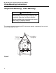
SECTION 1: SAFETY Safety Your Safety is Important to Us This symbol is used throughout these instructions to notify you of possible fire, electrical or shock hazards Please pay special attention when reading and following the warnings. WARNING WARNING Electrical Shock Hazard Vacuum pump must be installed and grounded according to national codes. Improper installation, adjustment, alteration, service or maintenance will result in death, injury or property damage.
EP-100 PUMP INSTALLATION, OPERATION AND SERVICE MANUAL Unpacking the Pump Contents of the EP-100 Pump Package Box 1 of 2: Part number 127102US Description Qty. Pump Frame, Motor and Impeller Assembly . . . . . . . . . . . . . . .1 CORAYVAC® Installation Manual . . . . . . . . . . . . . . . . . . . . . . . . . .1 Box 2 of 2: 02724200 02757001 91901300 91907300 91412800 92311600 Inlet Flange Assembly . . . . . . . . . . . . . . . . . . . . . . . . . . . . . . . . . . .1 Blower Housing (Scroll) . . . . .
SECTION 1: UNPACKING THE VACUUM PUMP Unpacking the Pump Unpack the Pump Examine shipping cartons for external damage. Note any damage in the presence of the carrier. Have the carrier initial the "noted" Bill of Lading. Orient vacuum pump shipping cartons with arrows on cartons pointing upward. Open cartons and remove packing inserts. Carefully remove vacuum pump components from the shipping cartons. CAUTION Do not lift the vacuum pump assembly by grasping the impeller.
EP-100 PUMP INSTALLATION, OPERATION AND SERVICE MANUAL Pump Assembly Instructions Determine Orientation of Pump Scroll An arrow is affixed to the outside of the pump scroll to indicate the direction of rotation of the impeller. The standard rotation of the impeller is in the counterclockwise direction. Rotation of the impeller is as viewed from the rear of the motor as shown in the Figure below. Note that the pump scroll outlet must always be positioned at the bottom horizontal position.
SECTION 3: VACUUM PUMP ASEMBLY INSTRUCTIONS Pump Assembly Instructions Step 2 Following installation of the pump scroll to the pump frame, attach the inlet plate assembly to the pump scroll as follows using the #10-24 Keps locknuts provided. Step 3 This vacuum pump is equipped with a restricter assembly which is used as a means of setting the system vacuum. See the appropriate system installation manual for additional information. a.
EP-100 PUMP INSTALLATION, OPERATION AND SERVICE MANUAL Pump Assembly Instructions Step 4 The Motor Shaft Seal (P/N 02757500) eliminates air leakage around the motor shaft and reduces the associated noise. Install the motor shaft seal as follows: a. Separate the motor shaft seal at the pre-cut score line. b. Wrap the shaft seal around the motor shaft hub as shown above. c. Secure the shaft seal in position with the adhesive strip provided.
SECTION 4: MOTOR WIRING Motor Wiring WARNING Electrical Shock Hazard Disconnect electrical power before installation or service. Failure to follow these instructions can result in death or electrical shock. IMPORTANT: Improper rotation of the impeller can produce only half of the vacuum required for proper system operation. Prior to Installation Prior to installing the pump into the heating system, it is recommended that operation and proper rotation of the impeller is verified.
EP-100 PUMP INSTALLATION, OPERATION AND SERVICE MANUAL Pump Mounting Instructions Suspension Mounting - Chain Mounting WARNING Securely hang vacuum pump according to this Installation, Operation, and Service Manual. Failure to follow these instructions can result in death, injury or property damage. The standard method of mounting the EP-100 vacuum pump is suspending it from a chain and venting through the roof.
SECTION 4: MOTOR WIRING Pump Mounting Instructions Wall Mounting Platform - Angle Assembly The alternate method of mounting the EP-100 vacuum pump is on an outside wall and venting directly through the wall. The optional Mounting Angle Package P/N 01312102 must be ordered if this method is used.
EP-100 PUMP INSTALLATION, OPERATION AND SERVICE MANUAL Pump Mounting Instructions Mounting Platform (Angle Assembly) Vacuum pump may be mounted by using mounting angles as shown in view "A" or "B". 11.5" 7" "A" "B" NOTE: Typical assembly shown. Two (2) assemblies per each vacuum pump required. 4" X 8" Boot 5/8" Diameter Mounitng Holes 7" 4" 5-6" Motor 10" 10.25" 4" X 8" Boot 3.75" 7.5" Vacuum Proving Switch Thimble (if applicable) 11.
SECTION 6: VACUUM PUMP VENTING INSTRUCTIONS Pump Venting Instructions WARNING Carbon Monoxide Hazard Vacuum pump must be vented to the outside. Vacuum pump must be installed according to this Installation, Operation, and Service Manual. Failure to follow these instructions will result in death or injury. Venting General Requirements Install the venting in accordance with the National Fuel Gas Code, ANSI Z223.1/NFPA-54 latest revision.
EP-100 PUMP INSTALLATION, OPERATION AND SERVICE MANUAL Pump Venting Instructions If the vent pipe is over 30' (9 m) long, insulate it to minimize condensation. Seal all discharge pipe joints with General Electric RTV 106 or Permatex Form-A-Gasket red high-temperature silicone adhesive or equivalent. For horizontal venting: 1. Vent must exit building not less than 7 feet above grade when located adjacent to public walkways. 2.
SECTION 6: VACUUM PUMP VENTING INSTRUCTIONS Pump Venting Instructions Side Wall Venting 25 feet and 3 elbows maximum 18" minimum40" maximum 4" Single Wall Pipe/Tube Approved Thimble (If Applicable) 18" minimum40" maximum Bird Screen (included w/ Pump Package) 4" Vent Terminal (P/N 02537801) Tjernlund VH1-4" Vent Terminal (P/N 90502100, or equivalent) 5" to 4" Reducer 6" to 5" Reducer 5" Single Wall Pipe Tjernlund VH1-6" Vent Terminal (or equivalent) 50 feet and 3 elbows maximum Figure 12 Vent Re
EP-100 PUMP INSTALLATION, OPERATION AND SERVICE MANUAL Servicing Instructions CAUTION Disassembly and removal/replacement of any pump components must be done by a service contractor or electrician qualified in the installation and service of gas-fired heating equipment. Failure to follow these instructions can compromise pump operation and void warranty. DANGER DANGER Risque de blessures graves Severe Injury Hazard Install guard before operating high speed rotating impeller.
SECTION 7: SERVICING INSTRUCTIONS Servicing Instructions Step 5 The (2) impeller set screws should be removed and reinstalled with a drop of thread locking sealant and remain unseated during initial re-assembly. Step 6 Slide the impeller onto the motor shaft end. Apply a drop of thread locking sealant to the threads of the retainer screw/washer assembly. Insert the retainer screw into the shaft so that it bottoms on the end of the shaft and hub of the impeller. Torque to 30 in/lbs.
EP-100 PUMP INSTALLATION, OPERATION AND SERVICE MANUAL Replacement Parts Replacement or spare parts may be ordered through your Roberts-Gordon representative/distributor. Figure 13 Description 1 2 3 4 5a 5b 5c 6 7 8 9 16 Part Number Motor (1/3 H.P.) . . . . . . . . . . . . . . . .90604600 Bird Screen w/clamp . . . . . . . . . . . .01312200 Ground Strap . . . . . . . . . . . . . . . . . .01370200 Mount . . . . . . . . . . . . . . . . . . . . . . . . .91906100 5/16"-18 Hex Nut . . . . . . . . . . . . .
SECTION 9: LIMITED WARRANTY Limited Warranty THE ROBERTS GORDON® EP-100 PUMP WARRANTY ROBERTS-GORDON WILL PAY FOR: ROBERTS GORDON® warrants to the original owneruser that this ROBERTS GORDON® product will be free from defects in material and workmanship. This warranty is limited to thirty-six (36) months from the date of purchase by the original consumer, or forty-two (42) months from date of shipment by Roberts-Gordon, whichever occurs first.