
Service manual


5
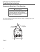
Pump Assembly Instructions
Step 2
Step 3
Following installation of the pump scroll to the pump frame, attach the inlet
plate assembly to the pump scroll as follows using the #10-24 Keps
locknuts provided.
This vacuum pump is equipped with a restricter assembly which is used as
a means of setting the system vacuum. See the appropriate system
installation manual for additional information.
a. When the pump is installed, be certain to lock the damper in the full
open position with the (1/4"-20) Hex Head bolt washers, and 5/16"
flatwasher. (See
Page 5, Figure 4
).
b. The inlet flange assembly is provided with a 1/8" N.P.T. tapping.
This is to be located at the top and used for connection of the
Vacuum Proving Switch (P/N 90430600) (See
Page 4, Figure 3
).
Damper Support Ass’y
(P/N 01329500)
1/4"-20 x 1/2 Hex Head Bolt
(P/N 93413008)
1/4" Ext. Tooth Lock Washer
(P/N 96211500)
5/16" Flat Washer
(P/N 95211600)
Inlet Flange Ass'y
(P/N 02724200)
Restricter Assembly
(P/N 01327500)
Figure 4
SECTION 3: VACUUM PUMP ASEMBLY INSTRUCTIONS