FOR YOUR SAFETY If you smell gas: 1. Open windows. 2. DO NOT try to light any appliance. 3. DO NOT use electrical switches. 4. DO NOT use any telephone in your building. 5. Extinguish any open flame. 6. Leave the building. 7. Immediately call your local gas supplier after leaving the building. Follow the gas supplier’s instructions. 8. If you cannot reach your gas supplier, call the Fire Department.
TABLE OF CONTENTS SECTION 1: Heater Safety...................................................... 1 1.1 Manpower Requirements ............................................. 1 1.2 Safety Labels and Their Placement ............................. 1 1.3 California Proposition 65 .............................................. 1 SECTION 2: Installer Responsibility ..................................... 4 2.1 Wall Tag ....................................................................... 4 2.2 Corrosive Chemicals....
TABLE OF FIGURES Figure 1: Top and Bottom Panel Label Placement .................... 2 Figure 2: Side and Back Panel Label Placement ...................... 3 Figure 3: Standard Reflector .................................................... 7 Figure 4: One Side Reflector.................................................... 7 Figure 5: Two Side Reflectors .................................................. 7 Figure 6: 45° Tilt Reflector .......................................................
SECTION 1: HEATER SAFETY SECTION 1: HEATER SAFETY Your Safety is Important to Us! This symbol is used throughout the manual to notify you of possible fire, electrical or burn hazards. Please pay special attention when reading and following the warnings in these sections. 1.1 Manpower Requirements To prevent personal injury and damage to the heater, two persons will be required for installation. 1.
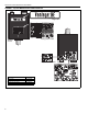
HE-SERIES INSTALLATION, OPERATION AND SERVICE MANUAL FIGURE 1: Top and Bottom Panel Label Placement Logo Label Rating Plate Label Bottom Panel Proposition 65 Label Description Logo Label Rating Plate Label Gas Connection Label Proposition 65 Label 2 Part Number 91013201 91010401 91018122 91070015 Top Panel
SECTION 1: HEATER SAFETY FIGURE 2: Side and Back Panel Label Placement Control Side Panel Clearances to Combustibles Label Control Side Panel (Inside) Wiring Label Vent Length Label Back Panel Lighting Instruction Plate Label Description Clearances to Combustibles Label Wiring Label Vent Length Label Lighting Instruction Plate Label Part Number 91013415 91013300 91039500 91029602 3
HE-SERIES INSTALLATION, OPERATION AND SERVICE MANUAL SECTION 2: INSTALLER RESPONSIBILITY The installer is responsible for the following: • To install the heater, as well as the gas and electrical supplies, in accordance with applicable specifications and codes. Roberts-Gordon LLC recommends the installer contact a Local Building inspector or Fire Marshal for guidance.
SECTION 2: INSTALLER RESPONSIBILITY 2.2 Corrosive Chemicals CAUTION Product Damage Hazard Do not use heater in area containing corrosive chemicals. Refer to appropriate Material Safety Data Sheets (MSDS). Failure to follow these instructions can result in product damage. Roberts-Gordon LLC cannot be responsible for ensuring that all appropriate safety measures are undertaken prior to installation; this is entirely the responsibility of the installer.
HE-SERIES INSTALLATION, OPERATION AND SERVICE MANUAL SECTION 3: CLEARANCES TO COMBUSTIBLES 3.1 Required Clearances to Combustibles WARNING Fire Hazard Keep all flammable objects, liquids and vapors the minimum required clearances to combustibles away from heater. Some objects will catch fire or explode when placed close to heater. Failure to follow these instructions can result in death, injury or property damage.
SECTION 3: CLEARANCES TO COMBUSTIBLES NOTE: 1. All dimensions are from the surfaces of all tubes, couplings and elbows. 2. Clearances B, C and D can be reduced by 50% after 25' (7.5 m) of tubing downstream from where the burner and burner tube connect.
HE-SERIES INSTALLATION, OPERATION AND SERVICE MANUAL NOTE: 1. All dimensions are from the surfaces of all tubes, couplings and elbows. 2. Clearances B, C and D can be reduced by 50% after 25' (7.5 m) of tubing downstream from where the burner and burner tube connect.
SECTION 4: NATIONAL STANDARDS AND APPLICABLE CODES SECTION 4: NATIONAL STANDARDS AND APPLICABLE CODES 4.1 Gas Codes The type of gas appearing on the nameplate must be the type of gas used. Installation must comply with national and local codes and requirements of the local gas company. United States: Refer to National Fuel Gas Code NFPA 54/ANSI Z223.1 - latest revision. Canada: Refer to Natural Gas and Propane Installation Code CSA B149.1 - latest revision. 4.
HE-SERIES INSTALLATION, OPERATION AND SERVICE MANUAL SECTION 5: MAJOR COMPONENTS FIGURE 13: Major Component Descriptions Burner with Tube Gasket Must be installed with the flame observation window facing down. Burner Tube Supplied in 10' (3 m) lengths. Burner tube is always the first tube after the burner. Reflector (Stainless Steel or Aluminum) Alternate overlap as shown on overview and on Page 19, Figure 17. Minimum overlap is 6" (16 cm).
SECTION 5: MAJOR COMPONENTS 5.1 Standard Parts List Table 1: Contents of Heater Burner Carton Part No.
HE-SERIES INSTALLATION, OPERATION AND SERVICE MANUAL Table 3: Component Package Guide Model Tubing Length HE-40 Core and Extension Packages Aluminized Stainless Steel 10' (3 m) CP10ALUM CP10ALUMSS HE-60 20' (6 m) CP20ALUM CP20ALUMSS HE-80 20' (6 m) CP20ALUM CP20ALUMSS HE-100 30' (9 m) CP30ALUM CP30ALUMSS HE-125 40' (12 m) CP40ALUM CP40ALUMSS HE-150 50' (15 m) CP30ALUM + EXP20ALUM CP30ALUMSS+ EXP20ALUMSS HE-175 60' (18 m) CP30ALUM + EXP30ALUM CP30ALUMSS + EXP30ALUMSS Table 4
SECTION 6: HEATER INSTALLATION SECTION 6: HEATER INSTALLATION WARNING Expansion and contraction of the tube dictates that the minimum suspension lengths in the table on Page 16, Figure 14 be maintained. Severe Injury Hazard Secure burner to burner tube with bolts and lockwashers. Hang heater with materials with a minimum working load of 75 lbs (33 kg). Failure to follow these instructions can result in death, injury or property damage.
HE-SERIES INSTALLATION, OPERATION AND SERVICE MANUAL FIGURE 14: Critical Hanger Placement (Indoor Installation) Typical Suspension Details Beam Clamp Anchor Screw Hook 3/8" 24" min.
SECTION 6: HEATER INSTALLATION 6.1 Outdoor Mounting may be parked within the clearances to The heater is meant for stationary mounting in all sit- combustibles. uations and should not be suspended from any struc- The bottom of the combustion air inlet shall not be less than 12" (30 cm) above a surface which could ture which may become mobile or from any organic structures such as trees. Clearances to combustibles support snow, ice, or debris. See Page 17, Figure 15.
18 * Reflector Vent Adapter Vent Cap Tube Turbulator (With Select Models) *Assembly shown with additional reflector supports as provided with stainless steel reflector packages.
SECTION 6: HEATER INSTALLATION FIGURE 17: Linear Heater Layout Overview b c g LEGEND d Burner Reflector f HE-40 Tube/Reflector Hanger b c g Tube 10' (3 m) Tube Length d Coupling Assembly e Vent Adapter a = 14" (36 cm) reflector width (not shown) f HE-60 HE-80 b = 2" (5 cm) end cap to burner 20' (6 m) Tube Length g b c c = 2" (5 cm) end cap to hanger d e e d = 7'6" (2.3 m) distance from first hanger to second hanger e = 10' (3 m) distance between hangers f g f = 9.
HE-SERIES INSTALLATION, OPERATION AND SERVICE MANUAL Step 6.2 Burner Tube Installation Hanging hardware shown is for indoor installation only. See Page 17, Figure 15 for outdoor suspension details. NOTE: Tubing requires a downward slope of 1/2" (1.3 cm) per 20' (6 m) away from burner. Offset mounting hole must be to the top. . S-hook Hanger Burner Tube Weld seam must be to the bottom of the tube.
SECTION 6: HEATER INSTALLATION Step 6.4 Coupling and Tube Assembly Close coupling A with tab Start Slide bar/Coupling Lock B onto coupling Tab Slide Bar/Coupling Lock Wide End Coupling Open 3" (8 cm) to 4" (10 cm) Closed C Insert tubes into coupling D Tighten coupling to join tubes Slide Bar/Coupling Lock Coupling Orient coupling so that the impact block is in the 2:00 or 10:00 oclock positions.
HE-SERIES INSTALLATION, OPERATION AND SERVICE MANUAL Step 6.4.2 Coupling and Tube Assembly (Continued) Model HE-40 HE-60 HE-80 HE-100 HE-125 HE-150 HE-175 Tube Length 10' (3 m) 20' (6 m) 20' (6 m) 30' (9 m) 40' (12 m) 50' (15 m) 60' (18 m) 7' 6" ± 1' (2.3 m ± .25 m) 10' ± 1' (3 m ± .25 m) Hanging hardware shown is for indoor installation only. See Page 17, Figure 15 for outdoor suspension details. Total Overall Tube Length Step 6.
SECTION 6: HEATER INSTALLATION Step 6.6 Reflector Installation WARNING Fire Hazard Support reflector with reflector hanger and support strap. Reflector must not touch tube. Failure to follow these instructions can result in death, injury or property damage. NOTE: All tube surfaces must be covered by a reflector, except for a U-Tube. Hanging hardware shown is for indoor installation only. See Page 17, Figure 15 for outdoor suspension details.
HE-SERIES INSTALLATION, OPERATION AND SERVICE MANUAL Step 6.6.1 Reflector, U-Clip and Reflector Support Installation The pictorial drawings of the heater construction in Section 6 are schematic only and provide a general guideline of where hangers, reflector supports and Uclips are to be installed. To ensure proper expansion and contraction movement of the reflectors, a combination of U-clips and reflector supports are used.
SECTION 6: HEATER INSTALLATION Step 6.7 Burner Installation Hanging hardware shown is for indoor installation only. See Page 17, Figure 15 for outdoor suspension details. Gasket S-hook Burner Tube Burner Description Bolt Burner Lock Washer Gasket Part Number 94273914 032XXXXX 96411600 02568200 Lock Washer Bolt (Torque 120 in/lb 13.
HE-SERIES INSTALLATION, OPERATION AND SERVICE MANUAL SECTION 7: OPTIONAL HEATER ACCESSORIES WARNING Cut/Pinch Hazard Wear protective gear during installation, operation and service. Edges are sharp. Failure to follow these instructions can result in injury. 7.1 U-Tube Configuration Heaters (except HE-40) are approved for optional UTube configurations.
SECTION 7: OPTIONAL HEATER ACCESSORIES FIGURE 18: U-Tube Heater Assembly Overview U-tube Support Bracket Reflector Support Vent Cap Vent Cap Burner Vent Adapter * Tube Clamp Package Burner Tube Turbulator (With Select Models) Tube Reflector U-tube, Standard 1 Couplings 2 * U-tube, Full 45° U-bolt 1 4"Tight (10 cm) U-bolt, 2 secured to burner tube with 1/4" (6 mm) lockwashers and 1/4"-20 hex nuts 2 Loose U-bolt 4" (10 cm) U-bolt, secured to bracket with 1/4" (6 mm) lockwashers and 1/4"-20
HE-SERIES INSTALLATION, OPERATION AND SERVICE MANUAL FIGURE 19: U-Tube heater Layout Overview 28
SECTION 7: OPTIONAL HEATER ACCESSORIES 7.2 Elbow Package Configuration Step 7.2.1 Elbow Installation Tube Coupling Description Elbow Package 90° Elbow Coupling Reflector End Cap Reflector Joint Piece U-Clip Package Part Number 02718702 01335801 01312700 02750800 02750900 91107720 90° Elbow Minimum Distance Required Between Burner and Elbow Model Minimum Distance HE-40 HE-60 10' (3 m) HE-80 10' (3 m) HE-100 15' (4.5 m) HE-125 15' (4.5 m) HE-150 15' (4.5 m) HE-175 15' (4.5 m) Step 7.2.
HE-SERIES INSTALLATION, OPERATION AND SERVICE MANUAL Step 7.2.4 Reflector Joint Installation Step 7.2.
SECTION 7: OPTIONAL HEATER ACCESSORIES 7.3 Reflector Side Extension (Not For Outdoor Use) Step 7.3.1 Bracket Installation Tube Reflector Tube and Reflector Hanger Reflector Support Reflector Side Extension Bracket (2 per Reflector) Use additional supports in high air movement applications. Description Reflector Side Extension Package Reflector Side Extension Retainer Clips Sheet Metal Screws Order Separately Reflector Side Extension Part Number 02712700 01368000 02751200 94118106 01329910 Step 7.3.
HE-SERIES INSTALLATION, OPERATION AND SERVICE MANUAL 7.4 Lower Clearance Shield Installation (Not For Outdoor Use) Step 7.4.1 Shield Support Strap Assembly Reflector 17" (43 cm) 12" (30 cm) Align Pilot Holes Lower Clearance Shield Locknuts Washers Screws Description Lower Clearance Shield Package Shield Support Strap Lower Clearance Shield 8' Locknut #8 Flat Washer #8 Screw #8 x 3/8" Part Number 01397501 01397500 02793000 92311400 95310800 93511406 7.
SECTION 7: OPTIONAL HEATER ACCESSORIES Step 7.5.2 Frame Shield Installation Description Deco Grille Shield Part Number 01365900 Step 7.5.3 Reflector Side Extension Installation for Decorative Grilles Distance "A" Minimum Maximum 2" (4 cm) 6" (15 cm) 6" (15 cm) 10" (26 cm) 10" (26 cm) 14" (37 cm) Extension Part No.
HE-SERIES INSTALLATION, OPERATION AND SERVICE MANUAL 7.6 Protective Grille Installation (Not For Outdoor Use) Step 7.6.1 Silicone Cap Installation Silicone Cap Description Grille Section Grille End Cap Silicone Cap Grille Finger Part Number 08050001 08050002 91915951-6P Step 7.6.2 Grille End Cap Installation B A Grille Grille End Cap C D Bend up 90°. Pull outward. Step 7.6.
SECTION 8: VENTING SECTION 8: VENTING FIGURE 21: Outdoor Vent Cap Installation WARNING Carbon Monoxide Hazard Heaters installed unvented must be interlocked with sufficient building exhaust. Heaters must be installed according to the installation manual. Failure to follow these instructions can result in death or injury. Burner Apply Silicone Sealant Vent Cap For outdoor installations, vent caps must be installed at inlet and flue end. (See Page 37, Section 8.7).
HE-SERIES INSTALLATION, OPERATION AND SERVICE MANUAL 8.1.1 United States Requirements Vent must terminate at least 3' (.9 m) above any forced air inlet located within 10' (3.1 m). FIGURE 22: Tube Termination Vent must terminate at least 4' (1.2 m) below, 4' (1.2 m) horizontally from, or 1' (.3 m) above any door, operable window, or gravity air inlet into any building. 8.1.2 Canadian Requirements The vent shall not terminate within 6' (1.8 m) of a mechanical air supply inlet to any building.
SECTION 8: VENTING 8.
HE-SERIES INSTALLATION, OPERATION AND SERVICE MANUAL 8.8 Horizontal Ventilation 4" (10 cm) Pipe Description Vent Terminal (Comb. Wall) Vent Terminal Vent Cap 4" (10 cm) Part Number 90502100 02537801-XX 90502300 8.
SECTION 8: VENTING 8.
HE-SERIES INSTALLATION, OPERATION AND SERVICE MANUAL 8.11 Common Vertical Venting Requirements: • Maximum of four heaters can be commonly vented through the roof. • Heaters must be of the same BTU output. • Heaters must be controlled by a common thermostat. • Connections to a common stack must be positioned to avoid direct opposition between streams of combustion gases. 8.
SECTION 8: VENTING pressure or corrosive contaminants, such as halogenated hydrocarbons, are present in the air, an outside combustion air supply to the heater is required. Seal all combustion air pipe joints. 8.12.1 Length Requirements Follow the constraints listed on Page 36, Section 8.6. Use of optional outside combustion air is not recommended with unvented heaters. The air supply duct may have to be insulated to prevent condensation on the outer surface.
HE-SERIES INSTALLATION, OPERATION AND SERVICE MANUAL 8.12.4 Vertical Outside Air Supply for Double Heater Installation Vent Cap Roof 6" (15 cm) Single Wall Pipe Flex Hose (Recommended) Burner Band Clamp (Recommended) Sweeping 'T' Connection Burner Flex Hose (Recommended) 4" (10 cm) Single Wall Pipe Requirements: • Heaters must be controlled by a common thermostat. 8.12.
SECTION 9: GAS PIPING SECTION 9: GAS PIPING WARNING Fire Hazard Tighten gas hose fittings to connect gas supply according to Figure 23. Gas hose can crack when twisted. Gas hose moves during normal operation. Use only 36" (91 cm) long connector of 1/2" or 3/4" nominal ID. Connector supplied with heater for U.S. models (not with Canadian models). Failure to follow these instructions can result in death, injury or property damage.
HE-SERIES INSTALLATION, OPERATION AND SERVICE MANUAL FIGURE 23: Gas Connection with Flexible Gas Hose CORRECT POSITIONS CAUTION Product Damage Hazard Shut-Off Valve (included with gas hose) must be parallel to burner gas inlet. The 3" (8 cm) displacement shown is for the cold condition. This displacement may reduce when the system is fired. Hold gas nipple securely with pipe wrench when attaching gas hose. Failure to follow these instructions can result in product damage.
SECTION 10: WIRING SECTION 10: WIRING DANGER Electrical Shock Hazard Disconnect electric before service. Heater must be properly grounded. Failure to follow these instructions can result in death or electrical shock. Heaters can be controlled using several methods. Normally thermostats are used to control the heaters but they can also be controlled by an Energy 10.1 Line Voltage Thermostat Wiring Management System. Section 10.
HE-SERIES INSTALLATION, OPERATION AND SERVICE MANUAL 10.3 Low Voltage Thermostat Wiring with Multiple Burners 10.4 Electrical Connection to the Burner Box using Line Voltage Thermostat on Control Connect wires together with suitable approved wire connections. Green L1 L2 White Black Green to Gnd. White to L2 Black to L1 Gnd.
SECTION 10: WIRING 10.5 For External Thermostat Connection Run two wires from low voltage thermostat through connections off the ends of the blue and purple wires conduit as shown. The purple wire from the valve and and strip the ends approximately 1/2" (1.3 cm). Conthe blue wire from the transformer have 1/4" (6 mm) nect these 2 wires to the thermostat wires using suitblade female electrical terminals, which are conable wire connectors. nected by a black jumper wire. Cut the female 10.
HE-SERIES INSTALLATION, OPERATION AND SERVICE MANUAL 10.
SECTION 11: OPERATION AND MAINTENANCE SECTION 11: OPERATION AND MAINTENANCE WARNING DANGER Electrical Shock Hazard Disconnect electric before service. Explosion Hazard Turn off gas supply to heater before service. Heater must be connected to a properly grounded electrical source. Burn Hazard Allow heater to cool before service. Cut/Pinch Hazard Wear protective gear during installation, operation and service. Tubing may still be hot Edges are sharp. after operation.
HE-SERIES INSTALLATION, OPERATION AND SERVICE MANUAL ation of the heating system, service and annual inspections must be done by a contractor qualified in the installation and service of gas-fired heating equipment. Turn off gas and electric supplies before performing service or maintenance. Allow heater to cool before servicing. Before every heating season, a contractor qualified in the installation and service of gas-fired heating equipment must perform a thorough safety inspection of the heater.
SECTION 11: OPERATION AND MAINTENANCE Reflector Support Straps Tubes Verify that the reflector support straps are securely clamped to tube and reflector. See Page 24, Step 6.6.1. Verify tight and loose screws at reflector overlaps. Make sure there are no cracks. Make sure tubes are connected and suspended securely. See Page 15, Section 6. Make sure there is no sagging, bending or distortion. Clean any debris from top of tubes or replace as required. Check the inside of the firing tube with a flashlight.
HE-SERIES INSTALLATION, OPERATION AND SERVICE MANUAL SECTION 12: TROUBLESHOOTING DANGER Electrical Shock Hazard Disconnect electric before service. Heater must be properly grounded. Failure to follow these instructions can result in death or electrical shock. WARNING Fire Hazard Keep all flammable objects, liquids and vapors the minimum required clearances to combustibles away from heater. Explosion Hazard Turn off gas supply to heater before service. Burn Hazard Allow heater to cool before service.
SECTION 12: TROUBLESHOOTING 12.1 Honeywell SmartValve® II Troubleshooting This heater is supplied with the Honeywell SmartValve® II control system. This system is equipped with a diagnostic function that will assist in performing troubleshooting. The LED (Light Emitting Diode) indicator at the top of the SmartValve® II control will flash in various patterns to indicate status. The LED status indication chart provided below gives a summary of possible faults.
HE-SERIES INSTALLATION, OPERATION AND SERVICE MANUAL 12.
No No TROUBLESHOOT ENDS If the problem persists, Or contact your ROBERTS GORDON® Independent Distributor. Yes Does burner run until the No call for heat ends? Yes Does the burner stay on? Yes Does the burner light? Yes After igniter warm-up period, does the valve click? Yes No Repair/correct wiring. Repair/correct wiring. Repair/correct wiring. Contact Roberts-Gordon LLC at www.rg-inc.com Check the continuity of the ground wire. Check the thermostat.
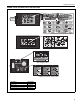
HE-SERIES INSTALLATION, OPERATION AND SERVICE MANUAL 12.3 Manifold Gas Pressure Setting Valve Outlet Valve Inlet Top View of Heater Manometer 56 5 6 6 5 4 3 2 1 0 1 2 3 4 5 6 Natural Gas LP Gas 6 5 4 3 2 1 0 1 2 3 4 3.5 in wc 10.
SECTION 13: REPLACEMENT PARTS SECTION 13: REPLACEMENT PARTS WARNING DANGER Electrical Shock Hazard Explosion Hazard Fire Hazard Carbon Monoxide Hazard Use only genuine ROBERTS GORDON® replacement parts per this installation, operation and service manual. Failure to follow these instructions can result in death, electric shock, injury or property damage.
HE-SERIES INSTALLATION, OPERATION AND SERVICE MANUAL Motor and Blower Assembly Blower Inlet Gasket Door Switch Burner Cup Assembly Mica Window Assembly Orifice Air Adapter Collar Gas Valve Hot Surface Igniter Pressure Switch Gas Valve Flame Sensor Tube Gasket Burner Side Air Pressure Tap 58 Transformer Blower Side Air Pressure Tap
SECTION 13: REPLACEMENT PARTS Description Gas Valve (Natural) Gas Valve (LP) Tube Gasket Blower Inlet Gasket Motor and Blower Assembly Air Adapter Collar Door Switch Burner Cup Assembly Hot Surface Igniter Mica Window Assembly Flame Sensor Transformer Gasket - Valve Pressure Switch: (175) (100) (80,150) (40, 60, 125) Part Number 90068300 90068302 02568200 03050900 90708600-P 91911700 90436800 03020100 90436603K 02553203 90439300 90436900K 03200100 90439802K 90439803K 90439810K 90439805K 59
HE-SERIES INSTALLATION, OPERATION AND SERVICE MANUAL SECTION 14: GENERAL SPECIFICATIONS 14.1 Material Specifications 14.1.1 Reflectors .024 Aluminum or .024 Stainless Steel Type 304 14.2 Heater Specifications 14.2.1 Ignition Honeywell® SmartValve® II combines gas valve and hot surface electronic ignition control. Fully automatic, four-try, 100% shut-off, prepurge, auto reset, LED indicator status. 14.3 Suspension Specifications Hang heater with materials with a minimum working load of 75 lbs (33 kg).
SECTION 15: THE ROBERTS GORDON® VANTAGE® HE WARRANTY SECTION 15: THE ROBERTS GORDON® VANTAGE® HE WARRANTY ROBERTS-GORDON LLC WILL PAY FOR: Within 36 months from date of purchase by buyer or 42 months from date of shipment by Roberts-Gordon LLC (whichever occurs first), replacement parts will be provided free of charge for any part of the product which fails due to a manufacturing or material defect. Roberts-Gordon LLC will require the part in question to be returned to the factory.