FOR YOUR SAFETY If you smell gas: 1. Open windows. 2. DO NOT try to light any appliance. 3. DO NOT use electrical switches. 4. DO NOT use any telephone in your building. 5. Extinguish any open flame. 6. Leave the building. 7. Immediately call your local gas supplier after leaving the building. Follow the gas supplier’s instructions. 8. If you cannot reach your gas supplier, call the Fire Department.
TABLE OF CONTENTS SECTION 1: Heater Safety ............................................2 1.1 Manpower Requirements ....................................2 1.2 IP55 Protection ....................................................2 1.3 Safety Labels and Their Placement ....................2 SECTION 2: Installer Responsibility............................4 2.1 Low Level User Instructions................................4 2.2 Corrosive Chemicals...........................................4 2.
TABLE OF FIGURES Figure 1: Bottom and Back Panel Label Placement ........2 Figure 2: Control Side Label Placement..........................3 Figure 3: Linear & Double Linear, Horizontal Mounts......6 Figure 4: Linear & Double Linear, One Side Reflector ....6 Figure 5: Linear & Double Linear, Two Side Reflectors ...6 Figure 6: Linear & Double Linear, 45° Mount ..................6 Figure 7: Linear & Double Linear, 2 Foot Deco Grille, Protective Grille ................................................
Product Approval ROBERTS GORDON® appliances have been tested and CE certified as complying with the essential requirements of the Gas Appliance Directive, the Low Voltage Directive, the Electromagnetic Compatibility Directive and the Machinery Directive for use on natural gas and LPG when installed, commissioned and maintained in accordance with these instructions. These instructions refer to appliances designed to operate in the European Union.
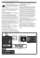
BLACKHEAT® HE INSTALLATION OPERATION AND SERVICE MANUAL SECTION 1: HEATER SAFETY 1.1 Manpower Requirements Your Safety is Important to Us! To prevent personal injury and damage to the heater, two persons will be required for installation. This symbol is used throughout the manual to notify you of possible fire, electrical or burn hazards. Please pay special attention when reading and following the warnings in these sections. 1.2 IP55 Protection The burner is certified to protection class of IP55.
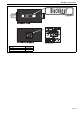
SECTION 1: HEATER SAFETY Figure 2: Control Side Label Placement Description Logo Label Wiring Diagram Label Part Number 91033200 91031404 3 of 73
BLACKHEAT® HE INSTALLATION OPERATION AND SERVICE MANUAL SECTION 2: INSTALLER RESPONSIBILITY • To install the heater, as well as the gas and electrical supplies, in accordance with applicable specifications and codes. Roberts-Gordon LLC recommends the installer contact a local Building Inspector or Fire Marshal for guidance. • To use the information given in a layout drawing and in the manual together with the cited codes and regulations to perform the installation.
SECTION 3: CLEARANCES TO COMBUSTIBLES SECTION 3: CLEARANCES TO COMBUSTIBLES WARNING • Consult local Building Inspector, Fire Insurance Carrier or other authorities for approval of proposed installation when there is a possibility of exposure to combustible airborne materials or vapours. • Hang heater in accordance to the minimum suspension requirements on Page 11, Section 5. Fire Hazard Keep all flammable objects, liquids and vapors the minimum required clearances to combustibles away from heater.
BLACKHEAT® HE INSTALLATION OPERATION AND SERVICE MANUAL 3.2 Clearances Data - Linear and Double Linear NOTE: 1. All dimensions are from the surfaces of all tubes, couplings, tees, elbows and crosses. 2. Clearances B, C and D can be reduced by 50% after 7500 mm of tubing downstream from the burner. 3. All measurements are in millimeters.
SECTION 3: CLEARANCES TO COMBUSTIBLES NOTE: 1. All dimensions are from the surfaces of all tubes, couplings, tees, elbows and crosses. 2. Clearances B, C and D can be reduced by 50% after 7500 mm of tubing downstream from the burner. 3. All measurements are in millimeters.
BLACKHEAT® HE INSTALLATION OPERATION AND SERVICE MANUAL 3.3 Clearances Data - U-Tube NOTE: 1. All dimensions are from the surfaces of all tubes, couplings, tees, elbows and crosses. 2. Clearances B, C and D can be reduced by 50% after 7500 mm of tubing downstream from the burner. 3. All measurements are in millimeters. 4. Add 60 mm clearance to uncovered u-tube. .
SECTION 3: CLEARANCES TO COMBUSTIBLES NOTE: 1. All dimensions are from the surfaces of all tubes, couplings, tees, elbows and crosses. 2. Clearances B, C and D can be reduced by 50% after 7500 mm of tubing downstream from the burner. 3. All measurements are in millimeters. 4. Add 60 mm clearance to uncovered u-tube.
BLACKHEAT® HE INSTALLATION OPERATION AND SERVICE MANUAL SECTION 4: MAJOR COMPONENT DESCRIPTIONS Burner (shown with Tube Gasket) Must be installed with the flame observation window facing down. Reflector (Aluminium or Stainless Steel) Alternate overlap as shown on overview. Minimum overlap is 160 mm. Burner Tube Tube Fan Tube with Internal Swirler Supplied in 3000 mm lengths. Burner tube is always the first tube after the burner. Heat treated aluminised tube supplied in 3000 mm lengths.
SECTION 5: GENERAL SUSPENSION DETAILS SECTION 5: GENERAL SUSPENSION DETAILS WARNING Severe Injury Hazard Secure burner to burner tube with bolts and lockwashers. Hang heater with materials with a minimum working load of 75 lbs (33 kg). Failure to follow these instructions can result in death, injury or property damage. WARNING Cut/Pinch Hazard Wear protective gear during installation, operation and service. Edges are sharp. Failure to follow these instructions can result in injury.
BLACKHEAT® HE INSTALLATION OPERATION AND SERVICE MANUAL Figure 17: Critical Hanger Placement Typical Suspension Details Beam Clamp I-Beam Concrete Beam Anchor I-Beam Washer 10 mm Rod 600 mm minimum* Screw Hook min. 10 mm Washer Locknut Wood Beam 300 mm minimum* Bow Shackle Turnbuckle (not included) * Allows for thermal expansion of system. Bow Shackle Side View Hanger Hanger 100 mm Max.
SECTION 6: LINEAR & DOUBLE LINEAR HEATER INSTALLATION SECTION 6: LINEAR & DOUBLE LINEAR HEATER INSTALLATION WARNING Cut/Pinch Hazard Wear protective gear during installation, operation and service. Edges are sharp. The figures in this section provide a general overview of component placement in a Linear and Double Linear system. The location of some components such as supports and couplings is crucial for proper installation. Assemble the heater components as shown on Page 14, Figure 18.
Vent Cap or Bird Screen 14 of 73 Burner Reflector End Cap Reflector Support Tube Clamp Package Burner Tube Tube and Reflector Hanger Coupling Outside Wall Fresh Air Supply Reflector *NOTE: Locate fan away from wet environment or use the IP54 protected fan.
SECTION 6: LINEAR & DOUBLE LINEAR HEATER INSTALLATION Figure 19: Linear Layout Overview g b c b d LEGEND e Burner HE15ST f Reflector Tube g b c b d Tube/Reflector Hanger e e Coupling Assembly HE20ST HE25ST f Fan Assembly Damper Assembly g b c b d e e e HE30ST HE35ST HE40ST f g b c b d e e e e HE45ST HE50ST f a b c d = = = = reflector width (not shown) - 365 mm end cap to burner/fan - 50 mm end cap to hanger - 50 mm distance first hanger - 2290 mm e = distance typical bet
BLACKHEAT® HE INSTALLATION OPERATION AND SERVICE MANUAL HE30DL HE40DL HE50DL HE60DL HE70DL 6.
Vent Cap or Bird Screen Outside Wall Burner Fresh Air Supply Reflector 1200 mm approx. Internal Swirler Weld Spot Tube and Reflector Hanger Reflector Support Burner Tube Tube Clamp Package Reflector End Cap Tube Clamp Package Coupling *NOTE: Locate fan away from wet environment or use the IP54 protected fan.
BLACKHEAT® HE INSTALLATION OPERATION AND SERVICE MANUAL Figure 21: Double Linear Layout Overview LEGEND g b c b d e Burner Reflector Repeated Opposite Side HE30DL f Tube Tube/Reflector Hanger Coupling Assembly g b c Fan Assembly b d e e HE40DL f HE50DL g b c Tee Assembly Repeated Opposite Side b d e e e Repeated Opposite Side HE60DL HE70DL f a b c d = = = = reflector width (not shown) - 365 mm end cap to burner/fan - 50 mm end cap to hanger - 50 mm distance first hanger - 2290
SECTION 6: LINEAR & DOUBLE LINEAR HEATER INSTALLATION Step 6.3 Burner Tube Installation Note: Tubing requires a downward slope of 13 mm per 6000 mm away from burner. Offset mounting hole must be to the top. Bow Shackle Hanger Burner Tube Weld seam must be to the bottom of the tube. 2290 mm ± 250 mm Description Burner Tube Bow Shackle Tube/Reflector Hanger Part Number 03051100 E0007576 03090100 Step 6.
BLACKHEAT® HE INSTALLATION OPERATION AND SERVICE MANUAL Step 6.4.1 Coupling and Tube Assembly (Continued) Tighten slide bar as shown below. Drive slide bar until tight. End of slide bar should be within tolerance listed below. ± 50 mm Correct Slide Bar dimensions Incorrect Slide Bar position • Repeat Step 6.4 A - D until all tubes are assembled. See Page 20, Section 6.4.2 shown below. Step 6.4.
SECTION 6: LINEAR & DOUBLE LINEAR HEATER INSTALLATION Step 6.
BLACKHEAT® HE INSTALLATION OPERATION AND SERVICE MANUAL Step 6.6 Reflector Installation WARNING Fire Hazard Support reflector with reflector hanger and support strap. Reflector must not touch tube. Failure to follow these instructions can result in death, injury or property damage.
SECTION 6: LINEAR & DOUBLE LINEAR HEATER INSTALLATION Step 6.6.1 Reflector, U-clip and Reflector Support Installation The pictorial drawings of the heater construction in Section 6 are schematic only and provide a general guideline of where hangers, reflector supports and u-clips are to be installed. To ensure proper expansion and contraction movement of the reflectors, a combination of u-clips and reflector supports are used.
BLACKHEAT® HE INSTALLATION OPERATION AND SERVICE MANUAL Step 6.
SECTION 7: U-TUBE HEATER INSTALLATION SECTION 7: U-TUBE HEATER INSTALLATION WARNING Cut/Pinch Hazard Wear protective gear during installation, operation and service. The figures in this section provide a general overview of component placement in a u-tube system. The location of some components such as supports and couplings is crucial for proper installation. Assemble the heater components as shown on Page 27, Figure 22.
HE15UT HE20UT HE25UT HE30UT HE35UT HE40UT HE45UT HE50UT BLACKHEAT® HE INSTALLATION OPERATION AND SERVICE MANUAL 96411500 Lockwasher 6mm 6 6 6 6 6 6 6 6 94320812 Screw #8 x 3/4, (Goes with 03050000) 4 8 8 8 8 8 12 12 Part No. S7199K Description Damper Flange Assembly (For use on Multiburner Systems) *PVC coating must be removed prior to installation. ** If an IP55 protected fan is required, this fan replaces 07260001, 07260002, or 07260003.
Vent Cap or Bird Screen *Fan Assembly Burner Burner Tube Weld Spot Tube Clamp 200 mm Package Maximum Outside Wall U-tube Support Bracket Fresh Air Supply (Required for Multiburner) Damper Assembly Flue Pipe or Optional Heat Exchanger (For Single Heater) Coupling Fan Tube Reflector *NOTE: Locate fan away from wet environment or use the IP54 protected fan.
BLACKHEAT® HE INSTALLATION OPERATION AND SERVICE MANUAL Figure 23: BLACKHEAT® HE U-tube Layout Overview h b c d LEGEND HE15UT Burner g Reflector h b c Tube d f Tube/Reflector Hanger Coupling Assembly HE20UT HE25UT g U-Tube h HE30UT HE35UT HE40UT a b c d = = = = d e d e g h HE45UT HE50UT b c b c f g overall width (not shown) - 850 mm end cap to burner/fan - 50 mm end cap to hanger - 50 mm distance first hanger - 2290 mm e = distance typical between hangers - 3050 mm f = dist
SECTION 7: U-TUBE HEATER INSTALLATION Step 7.2 U-tube Hanger Placement Spreader Bar Bow Shackle NOTE: Spreader bar must be used on single suspension point installations. Do not hang heater from spreader bar. Threaded Bar Suspension Chain Bow Shackle Washers Bolt (Torque: 13.
BLACKHEAT® HE INSTALLATION OPERATION AND SERVICE MANUAL Step 7.3.1 Tube Clamp Package Installation Weld Spot Bolt Nut (Torque: 13.56 Nm 120 in lb) Lock Washer Description Tube Clamp Package Tube Clamp Bolt Flat Washer Nut Tube Clamp Part Number 01318901 01396801 97113940 95211600 92113900 Step 7.
SECTION 7: U-TUBE HEATER INSTALLATION Step 7.5 Coupling and Tube Assembly coupling A Close with tab slide bar/coupling lock B Start onto coupling Tab Slide Bar Wide End Coupling Open 76 mm to 101 mm Closed D Tighten coupling to join tubes C Insert tubes into coupling Slide Bar Coupling Orient coupling so that the impact block is in the 2:00 or 10:00 oclock positions Tube Tube Description Coupling Slide Bar/Coupling Lock Tube Tube Part Number 01329600 01329700 91409408 Step 7.5.
BLACKHEAT® HE INSTALLATION OPERATION AND SERVICE MANUAL Step 7.6 Tube Installation Weld Spot Coupling Tube Step 7.
SECTION 7: U-TUBE HEATER INSTALLATION Step 7.8 Reflector Installation WARNING Fire Hazard Support reflector with reflector hanger and support strap. Reflector must not touch tube. Failure to follow these instructions can result in death, injury or property damage.
BLACKHEAT® HE INSTALLATION OPERATION AND SERVICE MANUAL Step 7.8.1 Reflector, U-clip and Reflector Support Installation The pictorial drawings of the heater construction in Section 6 are schematic only and provide a general guideline of where hangers, reflector supports and u-clips are to be installed. To ensure proper expansion and contraction movement of the reflectors, a combination of u-clips and reflector supports are used.
SECTION 8: MULTIBURNER CONFIGURATION & INSTALLATION SECTION 8: MULTIBURNER CONFIGURATION & INSTALLATION WARNING Severe Injury Hazard WARNING Cut/Pinch Hazard Secure burner to burner tube with bolts and lockwashers. Wear protective gear during installation, operation and service. Hang heater with materials with a minimum working load of 75 lbs (33 kg). Edges are sharp. Failure to follow these instructions can result in death, injury or property damage.
BLACKHEAT® HE INSTALLATION OPERATION AND SERVICE MANUAL Figure 25: Typical Manifold Layout (Linear and U-Tube Configuration) HE25UT HE25UT *Typical Fan Arrangement HE25UT 100 mm Manifold 150 mm Hanger 150 mm Manifold Max 3000 mm Tee (100 x 100 x 100) Damper (Typical) Cross Cross (100 x 150 x 100 x 150) Max 1000 mm ID/ID Sleeve (100 x 150 x 100 x 150) 100 mm Hanger NOTE: Be sure to silicone seal all manifold joints. Reducer (100 x 150) *Locate fan away from wet environment.
SECTION 9: BURNER & FAN INSTALLATION SECTION 9: BURNER & FAN INSTALLATION Step 9.1 Burner Installation NOTE: Tube Clamp Package not shown for clarity. For details, see Page 21, Step 6.5. Gasket Lock Washer Bolt (Torque: 13.5 Nm 120 in lb) Burner Description Bolt Lock Washer Gasket Burner Part Number 072600XX 96411600 02568200 033XXXXX Step 9.2 Standard Fan Assembly Fan Assembly Note: Apply Silicone (Recommended) Vent Adapter Install vent adapter with clamp in the up position.
BLACKHEAT® HE INSTALLATION OPERATION AND SERVICE MANUAL 9.3 IP55 Fan Assembly Fan Assembly Wire Gland (tighten securely) Note: Apply Silicone (Recommended) Vent Adapter Washer Install vent adapter with clamp in the up position. Description Fan Assembly Vent Adapter Nut M6 Washer M6 Nut (Torque: 2 Nm 18 in lb) Part Number 072600XX C1323B C0061B C0039B 9.4 Linear & U-tube Fan Installation Tighten securely until tube cannot be removed.
SECTION 9: BURNER & FAN INSTALLATION Step 9.5 Double Linear Fan Installation Tee Tighten securely until tube cannot be removed. Fan Assembly Step 9.5.
BLACKHEAT® HE INSTALLATION OPERATION AND SERVICE MANUAL Step 9.
SECTION 10: OPTIONAL HEATER ACCESSORIES SECTION 10: OPTIONAL HEATER ACCESSORIES WARNING Cut/Pinch Hazard Wear protective gear during installation, operation and service. Edges are sharp. Failure to follow these instructions can result in injury.
BLACKHEAT® HE INSTALLATION OPERATION AND SERVICE MANUAL 10.1 Reflector Side Extension Installation Step 10.1.1 Bracket Installation Tube Reflector Tube and Reflector Hanger Reflector Support Reflector Side Extension Bracket (2 per reflector) Use additional supports in high air movement applications. Description Reflector Side Extension Package Reflector Side Extension Retainer Clips Reflector Side Extension Part Number S7377K 01368000 02751200 01329910 Step 10.1.
SECTION 10: OPTIONAL HEATER ACCESSORIES 10.2 U-Tube Cover Installation The package contains two reflector joint pieces (P/N 02750901), one 8' reflector and 18 x #8 sheet metal screws. Install the u-tube cover using the following procedure. Step 10.2.1 Cut the 8' reflector in half to be used on both sides to cover the u-tube. Step 10.2.2 Flatten 4' reflector edge where joint piece matches. Put a mark on the 4' reflector, directly over the tube center.
BLACKHEAT® HE INSTALLATION OPERATION AND SERVICE MANUAL 10.3 Decorative Grille Installation Step 10.3.1 Grille Installation Description Aluminium Grille Part Number 91407000 Step 10.3.2 Frame Shield Installation Description Deco Grille Shield Part Number 01365900 Step 10.3.3 Reflector Side Extension Installation for Decorative Grilles Description Reflector Side Extension 44 of 73 Part Number 01370412 Distance "A" Minimum Maximum 40 mm 150 mm 150 mm 260 mm 260 mm 370 mm Extension Part No.
SECTION 10: OPTIONAL HEATER ACCESSORIES 10.4 Protective Grille Installation Step 10.4.1 Silicone Cap Installation Silicone Cap Grille Finger Description Grille Section Grille End Cap Silicone Cap Part Number 08050001 08050002 91915951-6P Step 10.4.2 Grille End Cap Installation Grille Grille End Cap A B Bend up 90°. C Pull outward. D Step 10.4.
BLACKHEAT® HE INSTALLATION OPERATION AND SERVICE MANUAL 10.5 Sports Hall Guard Installation Step 10.5.1 Grille Installation Strap - Stainless Steel Tube and Reflector Hanger Reflector Tube Description Mesh Guard 2438 mm Mesh Guard 1524 mm Strap Stainless Steel Part Number E0009855 C2329B S5218W Step 10.5.2 Fastener Installation Description Nut Spire Screw #8 x 3/8 Part Number C1088B C1089B Step 10.5.
SECTION 10: OPTIONAL HEATER ACCESSORIES 10.6 Undershield Installation 10.6.1 Hanger Installation Reflector Assembly Hanging Bracket Tube Hex Nut Stud Description Part Number Undershield Reflector Package 1010 mm S7399K Assembly Hanging Bracket C0318B Stud M6 x 90 C0693B Nut M6 C0090B 10.6.
BLACKHEAT® HE INSTALLATION OPERATION AND SERVICE MANUAL 10.7 Wall Mounting Install wall mounting brackets at the height shown in the layout drawing provided by the estimator. Space wall mounting brackets and hangers as indicated by dimensions d, e and f in the relevant Layout Overview drawing for your heater. For Linear heaters see Page 15, Figure 19, for Double Linear heaters see Page 18, Figure 21 and for u-tube heaters see Page 28, Figure 23. 10.7.
SECTION 11: VENTING AND FRESH AIR SUPPLY SECTION 11: VENTING AND FRESH AIR SUPPLY flue must be self supporting. Suitable terminals must be WARNING Carbon Monoxide Hazard Multiburner systems are not approved for unvented use and must be vented outdoors. Unitary heaters installed unvented must be interlocked with sufficient building exhaust. Heaters must be installed according to the installation manual. Failure to follow these instructions can result in death or injury.
BLACKHEAT® HE INSTALLATION OPERATION AND SERVICE MANUAL Figure 29: Individual Flue Connection Detail Fan Assembly Fan Tube Nut Lockwasher Screw (Torque: 2 Nm 18 in lb) Flue Adapter Flue Pipe Figure 30: Flue Connection Dimensions End of Tube C A Fan Tube Fan B Fan Model MB 56 2B M Torin DSF-133-42 Torin DSA-524-202 Magnetek JF1G A 98 mm 79 mm 86 mm 89 mm B 105 mm 95 mm 102 mm 102 mm C 52 mm 45 mm 51 mm 51 mm A Fan Part Number 90710051 (IP55) 76 mm 90710052 (IP55) 82 mm 90710053 (IP55) 82 mm B C
SECTION 11: VENTING AND FRESH AIR SUPPLY Figure 31: Air Supply with Flue Configurations C52 C12 C32 C12 C32 C62 B22 11.7 Common Duct When using a common air inlet duct, always ensure that the area of the common air inlet duct represents the area of all air ducts.
BLACKHEAT® HE INSTALLATION OPERATION AND SERVICE MANUAL SECTION 12: GAS PIPING WARNING Fire Hazard Tighten gas line fittings to connect gas supply according to Figure 32. Flex gas line can crack when twisted. Gas line moves during normal operation. Use only 1000 mm long connector of 1/2" or 3/4" nominal ID. Failure to follow these instructions can result in death, injury or property damage. WARNING Explosion Hazard Leak test all components of gas piping before operation.
SECTION 12: GAS PIPING Figure 32: Gas Connection with Stainless Steel Flex Connector CORRECT POSITIONS CAUTION Product Damage Hazard Shut-Off Valve (included with gas hose) must be parallel to burner gas inlet. The 80 mm displacement shown is for the cold condition. This displacement may reduce when the system is fired. Hold gas nipple securely with pipe wrench when attaching gas hose. Failure to follow these instructions can result in product damage. Vertical (as shown left) 30 mm 80 mm) max.
BLACKHEAT® HE INSTALLATION OPERATION AND SERVICE MANUAL SECTION 13: WIRING Description BLACKHEAT® HE Lockout Indicator Package Cable Gland Power Wire Blue Wire Brown Wire DANGER Part Number 03360008 U169 91300010 91300011 91300012 All wiring must comply with current wiring regulations and any local regulations which may apply. Always switch off the supply to the burner before removing the burner side panel. Electrical Shock Hazard Disconnect electric before service. Heater must be properly grounded.
SECTION 13: WIRING 13.2 Typical External Wiring Diagram (Double Linear Option 1) 230 V 1Ø 50 Hz L N L Controller or Thermostat N Earth 3A Fuse Earth Fan Burner 1 Burner 2 13.3 Typical External Wiring Diagram (Double Linear Option 2) 230 V 1Ø 50 Hz L N Controller or Thermostat L N Earth Earth Burner 1 Fan Burner 2 13.
BLACKHEAT® HE INSTALLATION OPERATION AND SERVICE MANUAL 13.
SECTION 14: OPERATION SECTION 14: OPERATION WARNING DANGER Electrical Shock Hazard Explosion Hazard Turn off gas supply to heater before service. Disconnect electric before service. Burn Hazard Cut/Pinch Hazard Allow heater to cool before service. Wear protective gear during installation, operation and service. Tubing may still be hot Edges are sharp. after operation. More than one disconnect switch may be required to disconnect electric from heater.
BLACKHEAT® HE INSTALLATION OPERATION AND SERVICE MANUAL Description Connector male - Lockout Indicator Connector female - Lockout Indicator Wire Blue 12" Wire Brown 12" Part Number 91324000 91324001 91300011 91300012 14.1.2 Heater Lockout Indicator by Volt Free Connector A volt free contact relay is closed which enables the ROBERTS GORDON® controller, BMS system, etc. to indicate the heater that has failed.
SECTION 15: SERVICING INSTRUCTIONS SECTION 15: SERVICING INSTRUCTIONS WARNING DANGER Electrical Shock Hazard Disconnect electric before service. Explosion Hazard Turn off gas supply to heater before service. More than one disconnect switch may be required to disconnect electric from heater. Burn Hazard Allow heater to cool before service. Cut/Pinch Hazard Wear protective gear during installation, operation and service. Tubing may still be hot Edges are sharp. after operation.
BLACKHEAT® HE INSTALLATION OPERATION AND SERVICE MANUAL 15.3.1 Electrode Figure 34: Burner Cup Position 15.3.4 Automatic Flame Control Unit Remove black ignition lead. Withdraw the 10 point edge connector. Unscrew two screws from the cover. Replace if faulty. Refit in reverse sequence. Burner Cup (center horizontally) 15.3.5 Pressure Switch 16 mm Electrode Assembly Disconnect the two silicone tubes. Remove electrical plug. Remove one screw which secures the pressure switch to the burner.
SECTION 15: SERVICING INSTRUCTIONS Vent Pipe Venting must be intact. Using a flashlight, look for obstructions, cracks on the pipe, gaps in the sealed areas or corrosion. The area must be free of dirt and dust. Remove any carbon deposits or scale using a wire brush. See Page 49, Section 11. Outside Air Inlet Inlet must be intact. Look for obstructions, cracks on the pipe, gaps in the sealed areas or corrosion. The area must be free of dirt and dust. Clean and reinstall as required.
BLACKHEAT® HE INSTALLATION OPERATION AND SERVICE MANUAL SECTION 16: TROUBLESHOOTING DANGER Electrical Shock Hazard Disconnect electric before service. Heater must be properly grounded. Failure to follow these instructions can result in death or electrical shock. WARNING Fire Hazard Keep all flammable objects, liquids and vapors the minimum required clearances to combustibles away from heater. Explosion Hazard Turn off gas supply to heater before service.
Is there spark at the igniter? Yes Turn up thermostat. Does the fan turn on? No No No Carefully reset gap to 3 mm. Replace electrode and ignition wire as needed. Replace automatic control unit. No Yes Is the igniter gap set at 3 mm? Check relay wiring (if applicable) and wiring to the burner. Check thermostat wiring and replace thermostat if necessary. Unplug burner and check electrode and ignition wire.
BLACKHEAT® HE INSTALLATION OPERATION AND SERVICE MANUAL Troubleshooting Flow Chart (Linear, Double Linear and U-Tube) 64 of 73
No After 20 second pre-purge Is there spark at the igniter? No Yes Turn up thermostat. Does the fan turn on? Yes Carefully reset gap to 3 mm. Replace electrode and ignition wire as needed. Replace automatic control unit. No Is the igniter gap set at 3 mm? Fan motor may have to be replaced. Is the clock set to on? Yes Unplug burner and check electrode and ignition wire. No Are they damaged? Check thermostat and replace if necessary.
BLACKHEAT® HE INSTALLATION OPERATION AND SERVICE MANUAL Troubleshooting Flow Chart (Multiburner) 66 of 73
SECTION 16: TROUBLESHOOTING 4 (12) 2 (14) 3 RELAY Control Chamber Combustion Chamber 16.3 Manifold Gas Pressure Setting 5(+) (A1) 1(-) (A2) Manometer 6 6 5 5 4 4 3 3 2 2 1 0 1 Governor (orifice) pressure while burner is running. See Page 73, Section 18.9.1. 1 0 Gas supply pressure while burner is running. See Page 71, Section 18.2.3.
BLACKHEAT® HE INSTALLATION OPERATION AND SERVICE MANUAL SECTION 17: REPLACEMENT PARTS WARNING DANGER Electrical Shock Hazard Explosion Hazard Fire Hazard Carbon Monoxide Hazard Use only genuine ROBERTS GORDON® replacement parts per this installation, operation and service manual. Failure to follow these instructions can result in death, electric shock, injury or property damage.
SECTION 17: REPLACEMENT PARTS N S B H A F Q(7) E R(4) V R(2) G V(2) W(3) C D R I V(2) W(2) J Q(6) K P L, T(2) Item Description A Automatic Control Unit B Flex Line Adapter Pressure Switch for HE50 C HE35 HE15, 20, 30, 45 HE25 D E* F G H I J K L M N HE40 Amber Neon Lamp Gas Valve Governor Screw Outlet Pressure Tap Cable Gland Star Washer Jet Orifice (See Page 73, Section 18.
BLACKHEAT® HE INSTALLATION OPERATION AND SERVICE MANUAL 17.1 Replacement Packages 17.1.1 Screw and Gasket Replacement Package (P/N 03360005) Description Screw M4 x 8mm Screw 10-24 x 5/8 Screw #8 x 3/8 Screw M8 x 20 mm Burner Tube Gasket Fresh Air Intake Gasket Rubber Gasket Gas Valve Gasket Quantity Part Number 2 93304506 4 93313100 4 94118107 2 93304507 1 92700004 1 92700005 10 92700002 1 03200100 17.1.
SECTION 18: SPECIFICATIONS SECTION 18: SPECIFICATIONS 18.1 Material Specifications 18.1.1 Combustion and Tubes 18.3 Venting Specifications 18.3.1 Fans 100 mm dia. 16 gauge heat treated aluminised mild steel. HE40, 45, 50 ................... Model: AO Smith JF1G 18.1.2 Reflectors HE50DL, 60DL,70DL ....... Model: Magnetek JF1G NS3 H14 aluminium or 1.4016 2R stainless steel (option). 18.2 Heater Specifications 18.2.
HE50ST HE45ST HE40ST HE35ST HE30ST HE25ST 18.6 Linear Heater HE20ST HE15ST BLACKHEAT® HE INSTALLATION OPERATION AND SERVICE MANUAL 35 40 45 50/51 Input - Net (kW) 13.5 18 22.5 27 31.5 36 40.
SECTION 18: SPECIFICATIONS 18.9 Burner Specifications Figure 35: BLACKHEAT® HE Linear and U-tube Specifications Reflector Fan End View Side View Swirler* 100 mm 241 mm Burner Tube 348 mm Tube Length 499 mm Damper Plan View Tube Length 100 mm Burner Tube Fan Damper 457 mm Fan Tube Internal Swirler* U-Tube *Swirler must always be located in Fan Tube. 18.9.
Attach this information to a wall near the ROBERTS GORDON® heater. ® I n f r a r e d H e a t i n g Read the Installation, Operation, and Service Manual thoroughly before installation, operation, or service. Know your model number and installed configuration. Model number and installed configuration are found on the burner and in the Installation, Operation and Service Manual.