FOR YOUR SAFETY If you smell gas: 1. Open windows. 2. DO NOT try to light any appliance. 3. DO NOT use electrical switches. 4. DO NOT use any telephone in your building. 5. Extinguish any open flame. 6. Leave the building. 7. Immediately call your local gas supplier after leaving the building. Follow the gas supplier’s instructions. 8. If you cannot reach your gas supplier, call the Fire Department.
TABLE OF CONTENTS SECTION 1: Introduction........................................................ 2 1.1 Safety Labels and Their Placement ............................. 2 1.2 What is a ROBERTS GORDON® NRG Control? .......... 2 1.3 General Requirements ................................................. 2 1.4 Control Location ........................................................... 2 1.5 Network Installation...................................................... 2 1.6 Installation Requirements................
TABLE OF FIGURES Figure 1: Keypad Layout ........................................................... 4 Figure 2: Remote Sensors ........................................................ 5 Figure 3: Cover Detail ............................................................... 6 Figure 4: Mounting Hole Layout ................................................ 6 Figure 5: Cable Entry ................................................................ 7 Figure 6: Control Terminals and Relay Use........................
Product Approval ROBERTS GORDON® appliances have been tested and CE certified as complying with the essential requirements of the Gas Appliance Directive, the Low Voltage Directive, the Electromagnetic Compatibility Directive and the Machinery Directive for use on natural gas, LPG and fuel oil when installed, commissioned and maintained in accordance with these instructions. These instructions refer to appliances designed to operate in the European Union.
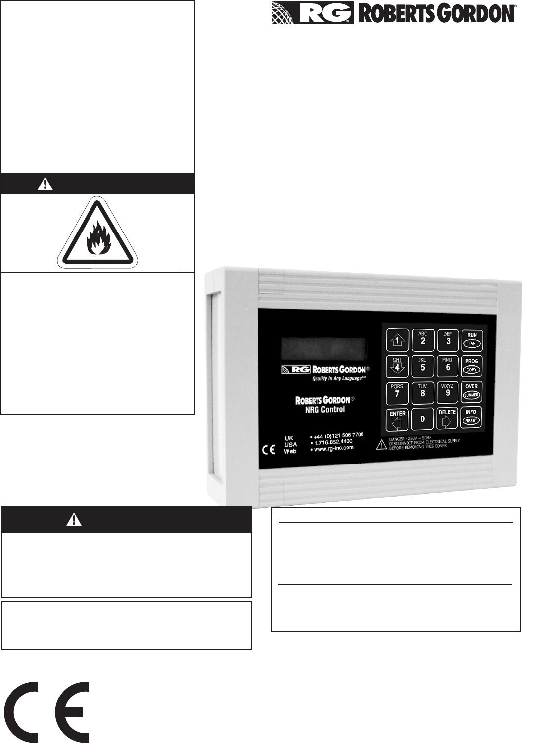
ROBERTS GORDON® NRG CONTROL INSTALLATION, OPERATION AND SERVICE MANUAL SECTION 1: INTRODUCTION Your Safety is Important to Us! This symbol is used throughout the manual to notify you of possible fire, electrical or burn hazards. Please pay special attention when reading and following the warnings in these sections. Installation, service and annual inspection of controller must be done by an electrician qualified in the installation and service of control systems for heating equipment.
SECTION 1: INTRODUCTION It will then be possible to set program times and temperatures for all controls from one location and copy programs from one control to another. It will also be possible to read the current status of all controls from a single station. 1.6 Installation Requirements 1.6.1 Radiant Tube Heaters The ROBERTS GORDON® NRG Control can operate up to ten burners providing that the electrical load on each relay does not exceed 7 A inductive.
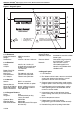
ROBERTS GORDON® NRG CONTROL INSTALLATION, OPERATION AND SERVICE MANUAL SECTION 2: SPECIFICATIONS Figure 1: Keypad Layout 10 1 4 1 ® Quality in Any Language™ 7 ® ENTER NRG Control RUN 2 3 5 8 0 6 9 SUMMER DELETE INFO 2 FAN PROG 3 COPY OVER 4 5 RESET 6 UK USA WEB • • • +44 (0)121 506 7700 1.716.852.4400 www.rg-inc.com DANGER - 230 V 50 Hz DISCONNECT FROM ELECTRICALSUPPLY BEFORE REMOVING THIS COVER 9 2.1 Material 2.1.1 Enclosure Enclosure Material: Weight: Dimensions: 2.1.
SECTION 2: SPECIFICATIONS 9. Enter key to confirm inputs (move backward around network). 10.Temperature adjustment (optional, between engineer defined limits) reverts to programmed set point at next switch on.
ROBERTS GORDON® NRG CONTROL INSTALLATION, OPERATION AND SERVICE MANUAL SECTION 3: INSTALLATION Figure 3: Cover Detail DANGER Clip Cover Screw Lid Assembly Electrical Shock Hazard Disconnect electric before service. Controller must be properly grounded to an electrical source. Failure to follow these instructions can result in death or electrical shock. Installation of ROBERTS GORDON® NRG Control must be done by an electrician qualified in the installation of control systems for heating equipment. 3.
SECTION 3: INSTALLATION 3.3.2 Ensure that Live, Neutral and Earth cables are looped three times through ferrite EMC filter as shown. Figure 5: Cable Entry Removable Plastic Entry Plate Figure 7: Ferrite EMC Filter Circuit Board Cut suitable holes 3.2.6 Install electrical wiring in accordance with the correct wiring diagram in Section 4 to wiring terminals as shown in Figure 6.
ROBERTS GORDON® NRG CONTROL INSTALLATION, OPERATION AND SERVICE MANUAL Figure 8: Sensor Mounting Plate - Warm Air Figure 10: Sports Hall Sensor Remote sensors must be fastened using countersunk screws. Dome headed screws will short out the board and result in failure of the sensor. Figure 9: Remote Temperature Sensor - Radiant Circuit Board Screws Cable Connections Cover Screws Cable Entry 3.3.7 Pressure Switch For CORAYVAC® systems only, a pressure switch is required to prove operation of system fan.
SECTION 4: WIRING SECTION 4: WIRING DANGER Electrical Shock Hazard Disconnect electric before service. More than one disconnect switch may be required to disconnect electric to the unit. Failure to follow these instructions can result in death or electrical shock. 4.
ROBERTS GORDON® NRG CONTROL INSTALLATION, OPERATION AND SERVICE MANUAL 4.
SECTION 4: WIRING 4.3 CTU Wiring (Pektron Ignition Controller) 4.
ROBERTS GORDON® NRG CONTROL INSTALLATION, OPERATION AND SERVICE MANUAL 4.5 CTU Wiring (Pactrol Ignition Controller) 4.
SECTION 4: WIRING 4.
ROBERTS GORDON® NRG CONTROL INSTALLATION, OPERATION AND SERVICE MANUAL 4.
SECTION 4: WIRING 4.
ROBERTS GORDON® NRG CONTROL INSTALLATION, OPERATION AND SERVICE MANUAL 4.10 MGB/MOB Range Wiring - 3 Ø Cabinet Heaters 4.
SECTION 4: WIRING 4.12 Cabinet Heater Remote Lockout Reset Wiring 4.
ROBERTS GORDON® NRG CONTROL INSTALLATION, OPERATION AND SERVICE MANUAL 4.14 CORAYVAC® and Multiburner Systems Wiring CAUTION Product Damage Hazard Do not directly connect control relay terminals to pump motor. Failure to follow these instructions can result in product damage.
SECTION 5: PROGRAMMING AND OPERATION SECTION 5: PROGRAMMING AND OPERATION 5.1 Stand Alone Unit The control has three basic levels of operation / programming. By default if a control is not connected to a network, then it assumes stand alone status. 1. Open level where access is open to anyone at all times. see Page 20, Section 5.3.2. 2. Manager level, where settings may be changed for normal operation, accessed through the manager code, which may be changed to one that can be remembered by the user.
ROBERTS GORDON® NRG CONTROL INSTALLATION, OPERATION AND SERVICE MANUAL 5.3.2 Default Settings The following settings are factory defaults and will be active following a system reset. Function Section Network Setting Default Setting Stand Alone Network Defaults Network Access Code Network Configuration Code Network ID Control Name Network Access Burner Lockout Reset from Network 5.6.1 5.6.1 5.6.1 5.6.1 5.6.
SECTION 5: PROGRAMMING AND OPERATION 5.
ROBERTS GORDON® NRG CONTROL INSTALLATION, OPERATION AND SERVICE MANUAL 5.4.1 Information 5.4.2 Lockout Reset WARNING Explosion Hazard If control locks out, do not make more than three attempts to restart the heater. Dangerous gas mixtures can build up. The fault must be traced and repaired by a registered installer or service engineer. Failure to follow these instructions can result in death, injury or property damage.
SECTION 5: PROGRAMMING AND OPERATION 5.4.3 Override and Summer Mode ZONE NAME 20°C SUMMER ZONE NAME 20°C HEAT OFF PRESS DEL OVER If user code programmed in engineer set up, then enter user code. SUMMER TO DELETE WRONG ENTRY ** WARNING! ** If user code not programmed in engineer set up, then access to next screen is open. ENTRY CODE: ???? ENTER 1) OVERRIDE MODE 2) SUMMER MODE Override allows extra time on or off outside of normal program.
ROBERTS GORDON® NRG CONTROL INSTALLATION, OPERATION AND SERVICE MANUAL 5.4.
SECTION 5: PROGRAMMING AND OPERATION 5.5 Manager Settings 5.5.
ROBERTS GORDON® NRG CONTROL INSTALLATION, OPERATION AND SERVICE MANUAL 5.5.2 Set Temperature ZONE NAME 20°C HEAT OFF PROG COPY Enter manager code four digits. Factory default code 0000. See engineer set up for alternative access to manager codes. ** WARNING! ** ENTRY CODE: ???? RUN Access from network. See Manager Settings Section Exit same route. ENTER FAN 1) TEMP 2) DATA 3) SYSTEM 4) HOLS Pres 1-4 for required option. PRESS RUN FAN 1 at any stage to escape.
SECTION 5: PROGRAMMING AND OPERATION 5.5.3 Set Operating Times Network Control Stand Alone Control ZONE NAME 20°C HEAT OFF PROG COPY ** WARNING! ** Exit to Network Enter from Network Control ENTRY CODE: ???? RUN ENTER FAN 1) TEMP 2) DATA 3) SYSTEM 4) HOLS Pres 1-4 for required option. RUN FAN Return from Network Control 2 SWITCH TIMES 1) SET 2) COPY 1 Set operating times from the Network Mon Period: 01 S:HH:MM E:HH:MM 2 Copy operating times from one to another or all.
ROBERTS GORDON® NRG CONTROL INSTALLATION, OPERATION AND SERVICE MANUAL 5.5.
SECTION 5: PROGRAMMING AND OPERATION 5.5.
ROBERTS GORDON® NRG CONTROL INSTALLATION, OPERATION AND SERVICE MANUAL 5.5.6 Set Holiday Period Network Control Stand Alone Control ZONE NAME 20°C HEAT OFF PROG COPY ** WARNING! ** ENTRY CODE: ???? RUN ENTER FAN Enter manager code four digits. Factory default code 0000. See engineer set up for alternatives access to manager codes. 1) TEMP 2) DATA 3) SYSTEM 4) HOLS Pres 1-4 for required option.
SECTION 5: PROGRAMMING AND OPERATION 5.6 Engineer Settings All engineer settings must be carried out at individual control. 5.6.
ROBERTS GORDON® NRG CONTROL INSTALLATION, OPERATION AND SERVICE MANUAL 5.6.
SECTION 5: PROGRAMMING AND OPERATION 5.6.
ROBERTS GORDON® NRG CONTROL INSTALLATION, OPERATION AND SERVICE MANUAL Table 1: Recommended Configuration Settings for Appliance Type Function Type ON/OFF Pressure Screen path from HI/LO High Flame Boost Switch Fan Purge Double Ignition Fan Options engineer code 4-1 4 - 1 - (1) 4-1-(0 or 2)-1 4 - 1 - (0, 1 or 2) 4-1-(0, 1 or 2) 4-2 Burner Options - Warm Air Heaters ON/OFF 0 N/A 0 0 0 See below High/Low Operation 1 1 N/A 0 0 See below Modulating Operation 2 N/A N/A 0 0 See below Fan Options - Warm Air Heate
SECTION 5: PROGRAMMING AND OPERATION 5.6.
ROBERTS GORDON® NRG CONTROL INSTALLATION, OPERATION AND SERVICE MANUAL 5.6.
SECTION 5: PROGRAMMING AND OPERATION 5.6.
ROBERTS GORDON® NRG CONTROL INSTALLATION, OPERATION AND SERVICE MANUAL 5.6.
SECTION 6: STANDARD SCREEN MESSAGES SECTION 6: STANDARD SCREEN MESSAGES 6.
ROBERTS GORDON® NRG CONTROL INSTALLATION, OPERATION AND SERVICE MANUAL 6.2 Network Control Screen Message ZONE NAME 20°C = This control currently being accessed by another network control. UNDER NW CONTROL NETWORK ERROR 01 KEYPAD LOCKED = This control cannot connect to the network. Check network wiring and configuration. See Network Wiring Section. = Network control that has been locked during network configuration. See Network Configuration Section. No access is allowed at this control.