
Service manual


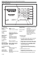

TABLE OF FIGURES
Figure 1: Keypad Layout ........................................................... 4
Figure 2: Remote Sensors ........................................................ 5
Figure 3: Cover Detail ...............................................................6
Figure 4: Mounting Hole Layout ................................................6
Figure 5: Cable Entry ................................................................ 7
Figure 6: Control Terminals and Relay Use............................... 7
Figure 7: Ferrite EMC Filter.......................................................7
Figure 8: Sensor Mounting Plate - Warm Air ............................8
Figure 9: Remote Temperature Sensor - Radiant .....................8
Figure 10: Sports Hall Sensor ................................................... 8