ROBERTS GORDON ® UltraVac ™ PATENTED Controls for Modulating CORAYVAC Infrared Heating Systems ® Installation Manual WARNING Improper installation, adjustment, alteration, service or maintenance can result in death, injury or property damage. Read the Installation, Operation and Service Manual thoroughly before installing or servicing this equipment. Installation must be done by an electrician qualified in the installation and service of control systems for heating equipment.
TABLE OF CONTENTS SECTION 1: Introduction........................................................ 2 1.1 Safety ........................................................................... 2 1.2 What is ROBERTS GORDON® ULTRAVAC™?............ 2 1.3 General Requirements ................................................. 2 1.4 CORAYVAC® Design Requirements............................. 2 1.5 Example Site Layout..................................................... 3 1.6 Check Installation Materials ................
TABLE OF FIGURES Figure 1: ULTRAVAC™ Controller Label Placement ................. 4 Figure 2: ULTRAVAC™ BMS Link Controller Label Placement 5 Figure 3: VFD Label Placement ................................................ 6 Figure 4: Repeater Label Placement ........................................ 7 Figure 5: Connected Components ............................................ 8 Figure 6: Example Site Layout ................................................
1 of 62
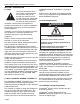
ROBERTS GORDON® ULTRAVAC™ CONTROLLER INSTALLATION MANUAL SECTION 1: INTRODUCTION 1.1 Safety Your Safety is Important to Us! This symbol is used throughout the manual to notify you of possible fire, electrical or burn hazards. Please pay special attention when reading and following the warnings in these sections. Installation, service and annual inspection of controller must be done by an electrician qualified in the installation and service of control systems for heating equipment.
SECTION 1: INTRODUCTION -ORCORAYVAC® systems designed shall have recommended radiant pipe length and 1.2 - 1.5 feet per flow unit of tailpipe length. See the CORAYVAC® Design Manual (P/N 127500NA) for minimum and recommended radiant pipe length. ERTS GORDON® independent distributor to obtain replacement signs or labels. See Page 4, Figure 1 through Page 7, Figure 4. 1.
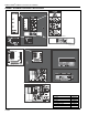
ROBERTS GORDON® ULTRAVAC™ CONTROLLER INSTALLATION MANUAL FIGURE 1: ULTRAVAC™ Controller Label Placement Light Label Electrical Shock Hazard Label L2 GRD L2 POWER L1 GRD L2 OUTPUT 1 L1 GRD L2 OUTPUT 2 L1 GRD L2 GRD L2 OUTPUT 4 L1 GRD OUTPUT 5 L1 L2 GRD OUTPUT 6 L1 L2 GRD OUTPUT 7 L1 L2 GRD OUTPUT 8 L1 OUTPUT 3 L1 Logo Label Rating Plate Label Front Door Panel (outside) External Wiring Label NC C NO NC C NO L2 L1 PWR OUT IN G +32 +5 G G G REF + - NC C NO REF OUT 2
SECTION 1: INTRODUCTION FIGURE 2: ULTRAVAC™ BMS Link Controller Label Placement Description Logo Label Rating Plate Label Light Label Control Board Wiring Label Shock Hazard label Part Number 91008017 91008016 91008015 91008014 91008001 5 of 62
ROBERTS GORDON® ULTRAVAC™ CONTROLLER INSTALLATION MANUAL FIGURE 3: VFD Label Placement Electrical Shock Hazard Label Side Panel (outside) Front Door Panel (outside) Rating Plate Label Variable Frequency Driver 1 Ø Input Model Shown B- Wiring Diagram Label U V W PE B+ Input Fuse Holder 17 PE 16 L2/N 1 2 5 6 11 13A 13B 13E 25 L1 Power Input Rotary Disconnect PE M16/12.
SECTION 1: INTRODUCTION FIGURE 4: Repeater Label Placement Description Wiring Diagram Label Logo Label Rating Plate Label Shock Hazard Label Part Number 91008020 91008021 91008022 91008001 7 of 62
ROBERTS GORDON® ULTRAVAC™ CONTROLLER INSTALLATION MANUAL FIGURE 5: Connected Components 8 of 62
SECTION 1: INTRODUCTION Connected Components (continued) 9 of 62
ROBERTS GORDON® ULTRAVAC™ CONTROLLER INSTALLATION MANUAL 1.
SECTION 1: INTRODUCTION URVCCM: ULTRAVAC™ Central Controller with Modem Line Voltage 120 V Wiring L1 POWER OUTPUT 1 OUTPUT 2 OUTPUT 3 OUTPUT 4 OUTPUT 5 OUTPUT 6 OUTPUT 7 OUTPUT 8 L2 GRD L1 L2 GRD L1 L2 GRD L1 L2 GRD L1 L2 GRD L1 L2 GRD L1 L2 GRD L1 L2 GRD L1 L2 GRD + - + - + - + 4 3 2 1 METER INPUTS RESET Modem Chip OH CD RI RESS Low Voltage 24 V Wiring NC C NO NC C NO L2 L1 PWR OUT IN G +32 +5 G G G REF + - NC C NO REF OUT 24VAC RS232 DIRECT + - + - + - + - + - NC C NO IN 4 3
ROBERTS GORDON® ULTRAVAC™ CONTROLLER INSTALLATION MANUAL URVCCR: ULTRAVAC™ Central Controller with RS-485 Converter Line Voltage 120 V Wiring L1 POWER OUTPUT 1 OUTPUT 2 OUTPUT 3 OUTPUT 4 OUTPUT 5 OUTPUT 6 OUTPUT 7 OUTPUT 8 L2 GRD L1 L2 GRD L1 L2 GRD L1 L2 GRD L1 L2 GRD L1 L2 GRD L1 L2 GRD L1 L2 GRD L1 L2 GRD + - + - + - + 4 3 2 1 METER INPUTS RESET Modem Chip OH CD RI RESS Low Voltage 24 V Wiring NC C NO NC C NO L2 L1 PWR OUT IN G +32 +5 G G G REF + - NC C NO REF OUT 24VAC RS232 DI
SECTION 1: INTRODUCTION URVBNC: ULTRAVAC™ BMS Link Controller ULTRAVAC™ BMS Link Controller Inside View ULTRAVAC™ Software (P/N 100816CDNA) contains: ULTRAVAC™ Software, ULTRAVAC™ Software Manual. (P/N 10081600NA) ULTRAVAC™ Installation Manual (P/N 10081601NA),BACnet® or MODBUS® Software 1.9 Standard Parts List Table 1: Contents of ULTRAVAC™ Controller and Accessories Part No.
ROBERTS GORDON® ULTRAVAC™ CONTROLLER INSTALLATION MANUAL Table 2: Common Components of ROBERTS GORDON® ULTRAVAC™ Controls Part No. Description Variable Frequency Drives* VFD75115 Variable Frequency Drive Assembly, .75 HP 115 V 1 Ø Input VFD75230 Variable Frequency Drive Assembly, .75 HP 230 V 1 Ø Input VFD20230 Variable Frequency Drive Assembly, 2 HP 230 V 1 Ø Input VFD75115N4 Variable Frequency Drive Assembly, .75 HP 115 V 1 Ø Input, NEMA 4 VFD75230N4 Variable Frequency Drive Assembly, .
Zone 1 Sensor Zone 1 Zone 2 Sensor Zone 2 ROBERTS GORDON® ULTRAVAC Controller Variable Frequency Drive Pump Zone 3 Outside Sensor Zone 3 Sensor North Wall SECTION 1: INTRODUCTION FIGURE 6: Example Site Layout NOTE: Conceptual drawing, not to scale. Venting not shown.
ROBERTS GORDON® ULTRAVAC™ CONTROLLER INSTALLATION MANUAL SECTION 2: SPECIFICATIONS 2.1 ROBERTS GORDON® ULTRAVAC™ Controller 2.1.1 Standard Enclosure Construction: 16 gauge painted steel, hinged door, removable knockouts provided. Dimensions: WxHxD (in): 14.7 x 17.7 x 3.5 (cm): 37.3 x 45.0 x 8.9 2.1.2 Electrical Power Supply: 120 V (+/- 10%) 1 Ø, 60 Hz UL Standard: UL 916 / C22.2 No. 205-M1983 Universal Inputs: Eight Universal Inputs Thermistor 0-10 Vdc 4-20m A Resistance Dry contact Link Controller.
SECTION 2: SPECIFICATIONS Enclosure: NEMA 4 gasketed aluminum LB housing, ½" threaded connection NEMA 4 Enclosure for Indoor Sensor (P/N 10081510) Description: NEMA 4 Enclosure is sold separately as an option. The indoor sensor is field mounted inside the NEMA 4 enclosure. Temperature thermistor and LCD temperature display will not operate properly inside the enclosure.
ROBERTS GORDON® ULTRAVAC™ CONTROLLER INSTALLATION MANUAL FIGURE 7: ROBERTS GORDON® ULTRAVAC™ Controller Specifications Note: To ensure robust control signaling: Do not run line voltage wiring through bottom section of enclosure that houses the control board. Do not run low voltage wiring through top section of enclosure that houses the relay board.
SECTION 2: SPECIFICATIONS 2.7 Variable Frequency Drive (VFD) 2.7.1 Enclosure Standard Models Construction: 14 gauge painted steel, mounting panel included, left-hinged door, vented. Dimensions: WxHxD (in): 12 x 14.375 x 8 (cm): 30.5 x 36.5 x 20.3 Protection: UL 50 Type 1, NEMA Type 1 NEMA 4 Models Description: Drive assembly and components fully factory assembled inside NEMA 4 enclosure. Enclosure dimensions and construction vary by model.
ROBERTS GORDON® ULTRAVAC™ CONTROLLER INSTALLATION MANUAL FIGURE 8: Variable Frequency Drive Components (Factory pre-wiring shown) 20 of 62
SECTION 3: INSTALLATION SECTION 3: INSTALLATION DANGER Electrical Shock Hazard Disconnect electric before service. Controller must be properly grounded to an electrical source. Failure to follow these instructions can result in death or electrical shock. Installation of the ROBERTS GORDON® ULTRAVAC™ Controller and the associated external electrical wiring must be done by an electrician qualified in the installation of control systems for heating equipment. 3.
ROBERTS GORDON® ULTRAVAC™ CONTROLLER INSTALLATION MANUAL 3.3 Cable Requirements: As per individual building specification for class of cable to be used. Use copper conductors only. 3.3.1 ULTRAVAC™ Controller Below is the recommended cable for the various connections for ULTRAVAC™ Controller: • Line Power Supply The power connection should be made with cable, size 14 AWG. • Eight Digital Output (Relays) The control connection for load of each individual relay should be made with cable, size 16 AWG.
SECTION 3: INSTALLATION 3.5 Pump Requirements The pump is powered directly from the Variable Frequency Drive (VFD). The VFD will be energized via an output from the relay board switched through a designated relay. 3.6 Variable Frequency Drive Requirements The VFD must be powered separately from the control enclosure. The 230 V drive power supply must be 230 V, 50-60 Hz, 1 Ø. The 120V drive power supply must be 120 V, 50-60 Hz, 1 Ø. The 480 drive power supply must be 480 V, 50-60 Hz, 3 Ø.
ROBERTS GORDON® ULTRAVAC™ CONTROLLER INSTALLATION MANUAL 3.7 Indoor Sensor Placement The sensor measures the air temperature in the building. It is important that the sensor is located in an area within the heated zone at occupant level. For the most accurate results, sensors should be mounted on an inside wall, away from any air vents or other sources of heat and cold.
SECTION 4: TYPICAL EXTERNAL DIAGRAMS SECTION 4: TYPICAL EXTERNAL DIAGRAMS DANGER Electrical Shock Hazard Disconnect electric before service. Controller must be properly grounded to an electrical source. Failure to follow these instructions can result in death or electrical shock.
ROBERTS GORDON® ULTRAVAC™ CONTROLLER INSTALLATION MANUAL FIGURE 13: ROBERTS GORDON® ULTRAVAC™ Central Controller External Wiring 26 of 62
SECTION 4: TYPICAL EXTERNAL DIAGRAMS ROBERTS GORDON® ULTRAVAC™ Central Controller External Wiring (continued) 27 of 62
ROBERTS GORDON® ULTRAVAC™ CONTROLLER INSTALLATION MANUAL FIGURE 14: ROBERTS GORDON® ULTRAVAC™ Satellite Controller External Wiring 28 of 62
SECTION 4: TYPICAL EXTERNAL DIAGRAMS ROBERTS GORDON® ULTRAVAC™ Satellite Controller External Wiring (continued) 29 of 62
ROBERTS GORDON® ULTRAVAC™ CONTROLLER INSTALLATION MANUAL SECTION 5: COMMUNICATIONS One ROBERTS GORDON® ULTRAVAC™ Controller per building (called the "central controller") must have equipment for remote communications to a PC. This equipment consists of either a modem chip, an RS-485 converter, or a TCP/IP communications module. shielded twisted pair communication wiring. See Page 31, Figure 16.
SECTION 5: COMMUNICATIONS 5.2 RS-485 Converter for Central Controller For remote on-site viewing of system status and settings of any controller, use the RS-485 converter to connect a single PC (9 pin serial port) to the RS485 terminals on the Central Controller. This will allow communication between one PC and any of the ULTRAVAC™ controllers on the network. For RS-485 converter wiring details see Page 31, Figure 16 and see Page 35, Section 5.5.
ROBERTS GORDON® ULTRAVAC™ CONTROLLER INSTALLATION MANUAL 5.3 TCP/IP Communication Module For remote on-site viewing of system status and settings of any controller, use the TCP/IP communication module to connect the controllers to a Local Area Network (LAN) via Ethernet cable. Any computer on the LAN that has ULTRAVAC™ software installed can be used to communicate with the controllers. The module must be mounted inside the ULTRAVAC™ central controller (controller #1) enclosure next to the control board.
SECTION 5: COMMUNICATIONS FIGURE 18: TCP/IP Communication Module Wiring It is important that the module power wire is connected as shown (black=5 V- / red= 5 V+) wire orientation. Make sure to verify connection before connecting to the control board. Description Kit, TCP/IP Communication Part Number 10080440K 5.4 Direct Connect For local viewing of system status and settings of any controller, a portable PC can be connected.
ROBERTS GORDON® ULTRAVAC™ CONTROLLER INSTALLATION MANUAL FIGURE 19: 9 Pin Adapter for PC Description PC Connection Cable Package 34 of 62 Part Number 10080410
SECTION 5: COMMUNICATIONS 5.5 Communications Between Multiple ROBERTS GORDON® ULTRAVAC™ Controllers If more than one ROBERTS GORDON® ULTRAVAC™ Controller is installed in a building, the controllers’ RS-485 communications must be wired in series. See Page 35, Figure 20. Connect the RS-485 terminal on controller #1 to the RS-485 terminal on controller #2 and so on in a daisy chain fashion. For communication cable requirements, See Page 22, Section 3.
ROBERTS GORDON® ULTRAVAC™ CONTROLLER INSTALLATION MANUAL 5.5.1 Repeater If the RS-485 communications wire length is above 4000' (1219 m), a repeater must be used to extend the signal. The repeater can also be used to install in different methods: • To extend communications beyond the standard 4000' (1219 m) limitation. See Page 36, Figure 21. • To add parallel branches of ROBERTS GORDON® ULTRAVAC™ controller communications bus wiring. See Page 37, Figure 22.
SECTION 5: COMMUNICATIONS FIGURE 22: Repeater Communication Wiring Between Multiple Controllers Description Repeater Part Number URVRP 37 of 62
ROBERTS GORDON® ULTRAVAC™ CONTROLLER INSTALLATION MANUAL SECTION 6: ULTRAVAC™ BMS LINK CONTROLLER Communication of data points from the ULTRAVAC™ 6.1 ULTRAVAC™ BMS Link Controller Overview Many customers have building management control system to the building controls system help allow systems that manage multiple mechanical systems in building managers and end users to easily integrate the building such as heating, ventilation, lighting, etc.
SECTION 6: ULTRAVAC™ BMS LINK CONTROLLER FIGURE 24: ULTRAVAC™ BMS Link Controller Schematic 6.2 ULTRAVAC™ BMS Link Controller Requirements The purpose of the ULTRAVAC™ BMS Link Controller is to integrate with a third party building control system. This building control system is provided by others and must be capable of communicating via one of the ULTRAVAC™ BMS Link communication protocols. For interface capability, one ULTRAVAC™ BMS Link Controller is needed for each ULTRAVAC™ network of controllers.
ROBERTS GORDON® ULTRAVAC™ CONTROLLER INSTALLATION MANUAL 6.3 Technical Data • Power Supply: 120 VAC. • Frequency: 50/ 60 Hz. • Network Cable: Standard Ethernet Cables. • Communication Ports: RS-485 Communication Bus • Memory: Memory Card, SD 1GB. 6.4 ULTRAVAC™ BMS Link Controller Programming Each ULTRAVAC™ BMS Link Controller is custom programmed before it is shipped. The custom program allows the controller to interface with the proper total number of ULTRAVAC™ Controls installed at the jobsite.
SECTION 6: ULTRAVAC™ BMS LINK CONTROLLER FIGURE 25: Communication Between ULTRAVAC™ BMS Link Controller and Multiple ULTRAVAC™ Controllers Controller Dip Switch Order (1,2,3,4,5,6,7,8) Address Controller Dip Switch Order (1,2,3,4,5,6,7,8) Address Number Values (1=ON, 0=OFF) Number Number Values (1=ON, 0=OFF) Number 1 (Central Controller) 2 3 4 5 6 7 8 9 10 01000000 2 11000000 00100000 10100000 01100000 11100000 00010000 10010000 01010000 11010000 3 4 5 6 7 8 9 10 11 11 12 13 14 15 16 17 18 19 20 001
ROBERTS GORDON® ULTRAVAC™ CONTROLLER INSTALLATION MANUAL SECTION 7: VARIABLE FREQUENCY DRIVE PROGRAMMING 7.1.2 7.1 VFD Parameter Settings For Use With ROBERTS GORDON® ULTRAVAC™ Use the arrow buttons to scroll to the password value The VFD parameters come with factory default settings. The following parameter settings must be changed for ROBERTS GORDON® ULTRAVAC™. Settings can only be altered when the pump motor is stopped.
SECTION 7: VARIABLE FREQUENCY DRIVE PROGRAMMING the password must be entered in order to access the parameters again. 7.2 Altering VFD Parameters Using the procedure described on Page 42, Section 7.1.1 through Section 7.1.5, alter the following parameters: Parameter Parameter Factory New Number Name Default Setting P01 Line Voltage 01 01 P03 Start Method 01 05 P05 Standard 01 (03) (0-10) Vdc Speed (04) (4-20) mA Source P44 Password 225 Any # 000-999 P45 Speed at 0.
ROBERTS GORDON® ULTRAVAC™ CONTROLLER INSTALLATION MANUAL SECTION 8: COMMISSIONING THE CORAYVAC® SYSTEM vacuum readings in the remaining branches are NOTE: The ROBERTS GORDON® ULTRAVAC™ software must be installed on the PC, the communi- proper. If necessary, adjust the proper damper coucation connection must be made to the controller and pling to achieve an end vent vacuum of 2.5" - 3.0" wc. all wiring of the ROBERTS GORDON® ULTRAVAC™ See Page 45, Figure 26.
SECTION 8: COMMISSIONING THE CORAYVAC® SYSTEM FIGURE 26: End Vent Vacuum Combustion Chamber at end burner position End Vent Insert tubing about 6" (15cm) into end vent. 6 5 4 3 2 1 0 1 2 3 4 Manometer 5 6 Approximate reading after adjusting VFD frequency setting and/or damper couplings. (~ ~ 2.
46 of 62 Damper Zone 1 Damper Coupling NOTE: Damper setting will vary Zone 1 Damper Coupling Zone 2 Zone 2 Damper Coupling Zone 1 End Vent Zone 3 Damper Coupling Pump Damper Zone 3 Zone 2 End Vent Zone 3 End Vent ROBERTS GORDON® ULTRAVAC™ CONTROLLER INSTALLATION MANUAL FIGURE 27: Possible Damper Couplings’ Locations
SECTION 8: COMMISSIONING THE CORAYVAC® SYSTEM Step 8.1.3 After setting end vent vacuums between 2.5" wc and 3.0" wc, while all the burners are still operating, use the down arrow button on the VFD to reduce the frequency of the output signal to the pump. Reduce the frequency of the VFD until the manometer at each of the end vents reads 1.0" wc 1.2" wc, Make note of this frequency setting below. The frequency is found on the VFD’s LCD screen. 1.0" w.c. - 1.
ROBERTS GORDON® ULTRAVAC™ CONTROLLER INSTALLATION MANUAL SECTION 9: TROUBLESHOOTING DANGER Electrical Shock Hazard Disconnect electric before service. More than one disconnect switch may be required to disconnect electric to the unit. Failure to follow these instructions can result in death or electrical shock. WARNING Explosion Hazard Turn off gas supply to heater before service. Failure to follow these instructions can result in death, injury or property damage.
SECTION 9: TROUBLESHOOTING FIGURE 28: Troubleshooting Flow Chart 49 of 62
ROBERTS GORDON® ULTRAVAC™ CONTROLLER INSTALLATION MANUAL Troubleshooting Flow Chart (continued) 50 of 62
SECTION 9: TROUBLESHOOTING Troubleshooting Flow Chart (continued) 51 of 62
ROBERTS GORDON® ULTRAVAC™ CONTROLLER INSTALLATION MANUAL Troubleshooting Flow Chart (continued) 52 of 62
SECTION 9: TROUBLESHOOTING FIGURE 29: Troubleshooting Flow Chart - Repeater 53 of 62
ROBERTS GORDON® ULTRAVAC™ CONTROLLER INSTALLATION MANUAL FIGURE 30: Troubleshooting Flow Chart - BACnet® 54 of 62
SECTION 10: REPLACEMENT PARTS SECTION 10: REPLACEMENT PARTS WARNING DANGER Electrical Shock Hazard Explosion Hazard Fire Hazard Carbon Monoxide Hazard Use only genuine ROBERTS GORDON® replacement parts per this installation, operation and service manual. Failure to follow these instructions can result in death, electric shock, injury or property damage.
ROBERTS GORDON® ULTRAVAC™ CONTROLLER INSTALLATION MANUAL 10.1 ROBERTS GORDON® ULTRAVAC™ Controller Replacement Parts Caution: Use only genuine ROBERTS GORDON® replacement parts. Use of parts not specified by Roberts-Gordon voids warranty.
SECTION 10: REPLACEMENT PARTS Part Number 07100 Description Relay 120 V Unitary Lights for 150 Style Control Board Lamp Green Enclosure Mount w/o Light Lamp Red Enclosure Mount w/o Light Light Diode 24 Vac 91321614 91321615 91321616 10.2 Variable Frequency Drive Replacement Parts Caution: Use only genuine ROBERTS GORDON® replacement parts. Use of parts not specified by Roberts-Gordon voids warranty.
ROBERTS GORDON® ULTRAVAC™ CONTROLLER INSTALLATION MANUAL 10.
SECTION 10: REPLACEMENT PARTS 10.
ROBERTS GORDON® ULTRAVAC™ CONTROLLER INSTALLATION MANUAL 10.5 Replacement Parts Instructions DANGER the doors. 10.5.4 24V Power 1 A Fuse To replace the 1 A fuse, turn off power to the relay board and turn off the 24 V power switch on the relay board. Electrical Shock Hazard Disconnect electric before service. Controller must be properly grounded to an electrical source. Failure to follow these instructions can result in death or electrical shock.
SECTION 10: REPLACEMENT PARTS pulling down the lever to expose the fuse. Remove the old fuse and insert a new fuse. Verify the correct fuse rating, 25 A for 1 HP 120 V VFD or 2 HP 230 V VFD, 10 A for the.75 HP 230 V VFD, 1 HP 480 V VFD and 2 HP 480 V VFD. Close the fuse holder. Return power to the VFD assembly and verify that the VFD LCD screen is on. (dashes displayed). Close the VFD assembly door. Return 120 V power to the relay board. Turn on 24 V power switch on the relay board.
ROBERTS GORDON® ULTRAVAC™ CONTROLLER INSTALLATION MANUAL SECTION 11: THE ROBERTS GORDON® ULTRAVAC™ LIMITED WARRANTY Within 36 months from date of purchase by buyer or 42 months from date of shipment by Roberts-Gordon (whichever occurs first), replacement parts will be provided free of charge for any part of the product which fails due to a manufacturing or material defect. Roberts-Gordon will require the part in question to be returned to the factory.