ROBERTS GORDON ® UltraVac ™ Controls for Modulating CORAYVAC Infrared Heating Systems ® Installation Manual WARNING Improper installation, adjustment, alteration, service or maintenance can result in death, injury or property damage. Read the installation and operation manuals thoroughly before installing or servicing this equipment. Installation must be done by an electrician qualified in the installation of control systems for heating equipment.
TABLE OF CONTENTS SECTION 1: Introduction........................................................ 1 1.1 What is ROBERTS GORDON® ULTRAVAC™? ........... 1 1.2 CORAYVAC® Design Requirements ............................ 1 1.3 General Requirements................................................. 1 1.4 Check Installation Materials......................................... 1 1.5 Carton Contents .......................................................... 2 1.6 Safety...................................................
TABLE OF FIGURES Figure 1: Example Site Layout .................................................. 6 Figure 2: ROBERTS GORDON® ULTRAVAC™ Controller Specifications ............................................ 8 Figure 3: Variable Frequency Drive Components ..................... 9 Figure 4: Controller Mounting ................................................. 10 Figure 5: Indoor Sensor Cable Detail......................................
SECTION 1: INTRODUCTION SECTION 1: INTRODUCTION 1.1 What is ROBERTS GORDON® ULTRAVAC™? The ROBERTS GORDON® ULTRAVAC™ is a micro processor based control package designed for modulating control of CORAYVAC® heaters based on outdoor temperatures. This controller is capable of giving control outputs to one vacuum pump and three heating zones. The controller also features inputs which are used for indoor and outdoor signal condition monitoring. 1.4 Check Installation Materials 1.4.
ROBERTS GORDON® ULTRAVAC™ CONTROLLER INSTALLATION MANUAL 1.
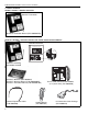
SECTION 1: INTRODUCTION URVCCM: UltraVac™ Central Controller with Modem Controller Enclosure Line Voltage 120 V wiring L1 POWER OUTPUT 1 OUTPUT 2 OUTPUT 3 OUTPUT 4 OUTPUT 5 OUTPUT 6 OUTPUT 7 OUTPUT 8 L2 GRD L1 L2 GRD L1 L2 GRD L1 L2 GRD L1 L2 GRD L1 L2 GRD L1 L2 GRD L1 L2 GRD L1 L2 GRD modem chip Low Voltage 24 V wiring UltraVac™ Controller with Modem Installed UltraVac™ Software (P/N 10080421) UltraVac™ Software Manual (P/N 10081600NA) UltraVac™ Installation Manual (P/N 10081601NA) Comms Equalization
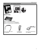
ROBERTS GORDON® ULTRAVAC™ CONTROLLER INSTALLATION MANUAL URVCCR: UltraVac™ Central Controller with RS-485 Converter Controller Enclosure Line Voltage 120 V wiring L1 POWER OUTPUT 1 OUTPUT 2 OUTPUT 3 OUTPUT 4 OUTPUT 5 OUTPUT 6 OUTPUT 7 OUTPUT 8 L2 GRD L1 L2 GRD L1 L2 GRD L1 L2 GRD L1 L2 GRD L1 L2 GRD L1 L2 GRD L1 L2 GRD L1 L2 GRD modem chip Low Voltage 24 V wiring UltraVac™ Controller with Modem Installed UltraVac™ Software (P/N 10080421) UltraVac™ Software Manual (P/N 10081600NA) UltraVac™ Installation
SECTION 1: INTRODUCTION 1.6 Safety Your Safety is Important to Us! This symbol is used throughout the manual to notify you of possible fire, electrical or burn hazards. Please pay special attention when reading and following the warnings in these sections. Installation, service and annual inspection of controller must be done by an electrician qualified in the installation and service of control systems for heating equipment.
ROBERTS GORDON® ULTRAVAC™ CONTROLLER INSTALLATION MANUAL Zone 1 Sensor Zone 1 Zone 2 Sensor Zone 2 ROBERTS GORDON® ULTRAVAC Controller Pump Zone 3 Variable Frequency Drive Outside Sensor Zone 3 Sensor North Wall FIGURE 1: Example Site Layout NOTE: Conceptual drawing, not to scale. Venting not shown.
SECTION 2: SPECIFICATIONS SECTION 2: SPECIFICATIONS 2.1 ROBERTS GORDON® ULTRAVAC™ Controller 2.1.1 Enclosure Construction: 16 gauge painted steel, hinged door, removable knockouts provided. Dimensions: 14.7" w x 17.7" h x 3.5" d 2.1.2 Electrical - Control Board Power Supply: 24 V 60 Hz (from relay board) Analog Inputs: Sensor (thermistor), BMS enable (dry contact) Relay Outputs: 24 Vac Analog Outputs: 0-10 Vdc Digital Inputs: Timed, dry contact Network Ports: RS-485, RS-232 UL Standard: UL 916 / C22.
ROBERTS GORDON® ULTRAVAC™ CONTROLLER INSTALLATION MANUAL FIGURE 2: ROBERTS GORDON® ULTRAVAC™ Controller Specifications 120 Vac Outputs 120 Vac Power Input 24 V Power 1 A Fuse L1 Relay Board POWER OUTPUT 1 OUTPUT 2 OUTPUT 3 OUTPUT 4 OUTPUT 5 OUTPUT 6 OUTPUT 7 OUTPUT 8 L2 GRD L1 L2 GRD L1 L2 GRD L1 L2 GRD L1 L2 GRD L1 L2 GRD L1 L2 GRD L1 L2 GRD L1 L2 GRD 24 V Power Switch Plug-In Relays 24 V Control Board Power Supply 24 V Input Connections Transformer 24 V RS 232 Board Direct Control 24 V Power C
SECTION 2: SPECIFICATIONS 2.3 Variable Frequency Drive (VFD) 2.3.1 Enclosure Construction: .75 HP, 230 V Drive (used with EP-203 pump) 208/240 V 1 Ø 50-60 Hz 14-gauge painted steel, mounting Power Input: panel included, left-hinged door, Input Voltage Tolerance: +/- 10% Amps: 6.9/6.0 A vented. Dimensions: 8" w x 10" h x 8" d Protection: 2.3.
ROBERTS GORDON® ULTRAVAC™ CONTROLLER INSTALLATION MANUAL SECTION 3: INSTALLATION WARNING Mounting Hazard Mount controls with materials with a minimum working load of 75 lbs (33 kg). Failure of the supports can result in death, injury or property damage. Note that the maximum distance from the controller to any sensor is 300' (120 m). For longer distances, larger gauge wire may be needed.
SECTION 3: INSTALLATION 3.3 Cable Requirements: 3.3.1 Line Power Supply: FIGURE 5: Indoor Sensor Cable Detail Insulation As per individual building specification for class of cable to be used. Use copper conductors only. To size the cable, use the amperages of the burners given on Page 12, Section 3.4.1, for each individual zone. 3.3.
ROBERTS GORDON® ULTRAVAC™ CONTROLLER INSTALLATION MANUAL FIGURE 7: RS-485 Communications Cable Detail Uninsulated Shield Wire Insulation Foil Shield 22 AWG Minimum 3.4 Electrical Installation Requirements DANGER Electrical Shock Hazard Disconnect electrical power before servicing. This appliance must be connected to a properly grounded electrical source. Failure to follow these instructions can result in death or electrical shock. 3.
SECTION 3: INSTALLATION 3.7 Indoor Sensor Placement The sensor measures the air temperature in the building. It is important that the sensor is located in an area within the heated zone at occupant level. For the most accurate results, sensors should be mounted on an inside wall, away from any air vents or other sources of heat and cold.
ROBERTS GORDON® ULTRAVAC™ CONTROLLER INSTALLATION MANUAL 3.8 Outdoor Sensor Placement The outdoor sensor measures air temperature outside the building. It is important that the sensor is located on the outside of the building on the north facing wall. Failure to mount the sensor on the north facing wall will result in artificially high temperature readings. If possible, locate the sensor high under an eve to prevent incorrect readings from direct sunlight and damage due to the elements.
SECTION 4: TYPICAL EXTERNAL DIAGRAMS SECTION 4: TYPICAL EXTERNAL DIAGRAMS FIGURE 11: Central Controller Communication Equalization Wiring 120 ohm resistor + - + - REF BLACK This connector will plug into the right set of RS-485 +/- terminals on this board as shown. RED All UltraVac™ Central Controllers are shipped with a communication equalization cable (P/N 10080450), satellite controllers do not use the cable.
ROBERTS GORDON® ULTRAVAC™ CONTROLLER INSTALLATION MANUAL FIGURE 12: ROBERTS GORDON® ULTRAVAC™ Central Controller External Wiring To Satellite Controller RS-485 (see NOTE 2) SEN SET O/R - + Zone 2 Sensor Outdoor Sensor SEN SET O/R - + POWER OUTPUT 1 OUTPUT 2 OUTPUT 3 OUTPUT 4 OUTPUT 5 OUTPUT 6 OUTPUT 7 OUTPUT 8 L1 L2 GRD L1 L2 GRD L1 L2 GRD L1 L2 GRD L1 L2 GRD L1 L2 GRD L1 L2 GRD L1 L2 GRD L1 L2 GRD Zone 1 Sensor NC C NO c + c + c + c + 5 6 7 8 24VAC Outputs 24V VAC RS-485 + - + - REF Modem Chip
SECTION 4: TYPICAL EXTERNAL DIAGRAMS FIGURE 13: ROBERTS GORDON® ULTRAVAC™ Central Controller External Wiring (continued) Outside Air Blower (optional) Zone 3 Burners Zone 2 Burners Zone 1 Burners L2 L1 L2 L1 L2 L1 L2 L1 L2 L1 L2 L1 L2 L1 L2 L1 L2 L1 Continued From Previous Page VFD Power Supply (see NOTE 3) VFD Assembly L1 L2/N PE B- B+ EPM To Terminal 5 To Terminal 2 Mode T1 U V W PE PE To Terminals 13 and 14 T2 T3 Vacuum Pump 230 V 3Ø 0-60 Hz Motor Power Supply (see NOT
ROBERTS GORDON® ULTRAVAC™ CONTROLLER INSTALLATION MANUAL FIGURE 14: ROBERTS GORDON® ULTRAVAC™ Satellite Controller External Wiring To Satellite Controller RS-485 (See NOTE 2) METER INPUTS + 2 + 3 + 4 - + 1 - - + - + - + - + 1 2 3 4 See NOTE 2 Separate line and low voltage circuits. Do not run line voltage wiring through bottom section of enclosure that houses the control board. Do not run low voltage wiring through top section of enclosure that houses the relay board.
SECTION 4: TYPICAL EXTERNAL DIAGRAMS FIGURE 15: ROBERTS GORDON® ULTRAVAC™ Satellite Controller External Wiring (continued) Outside Air Blower (optional) Zone 3 Burners Zone 2 Burners Zone 1 Burners L2 L1 L2 L1 L2 L1 L2 L1 L2 L1 L2 L1 L2 L1 L2 L1 L2 L1 Continued From Previous Page VFD Power Supply (see NOTE 3) VFD Assembly L1 L2/N PE B- B+ EPM To Terminal 5 To Terminal 2 Mode T1 T2 T3 U V W PE PE To Terminals 13 and 14 Vacuum Pump 230 V 3Ø 0-60 Hz Motor Power Supply (See NO
ROBERTS GORDON® ULTRAVAC™ CONTROLLER INSTALLATION MANUAL SECTION 5: COMMUNICATIONS One ROBERTS GORDON® ULTRAVAC™ Controller per building must have equipment for remote communications to a PC. This equipment consists of either a modem chip, an RS-485 converter, or a TCP/ IP communications module. shielded twisted pair communication wiring. See Page 21, Figure 17. To interface with ULTRAVAC™ controllers through a Local Area Network (LAN), a TCP/IP Communication module is installed at controller #1.
SECTION 5: COMMUNICATIONS 5.2 RS-485 Converter for Central Controller For remote on-site viewing of system status and settings of any controller, use the RS-485 converter to connect a single PC (9 pin serial port) to the RS-485 terminals on the Central Controller. This will allow communication between one PC and any of the ULTRAVAC™ controllers on the network. For RS-485 converter wiring details see Page 21, Figure 17 and see Page 25, Section 5.5 Section 3.3.5.
ROBERTS GORDON® ULTRAVAC™ CONTROLLER INSTALLATION MANUAL 5.3 TCP/IP Communication Module For remote on-site viewing of system status and settings of any controller, use the TCP/IP communication module to connect the controllers to a Local Area Network (LAN) via Ethernet cable. Any computer on the LAN that has ULTRAVAC™ software installed can be used to communicate with the controllers. The module must be mounted inside the ULTRAVAC™ central controller (controller #1) enclosure next to the control board.
SECTION 5: COMMUNICATIONS FIGURE 19: TCP/IP Communication Module Wiring 120 ohm resistor (included) + - + - REF RED BLACK Standard 4 Wire Phone Cord (included) METER INPUTS RS-485 RS-232 Direct Port Dip Switch #1 set to ON 3 2 +5 +16 8 7 6 5 4 3 2 1 1 + - + - + - + - + - + - + - + - GND + + + + - 4 Shrinkwrap Ethernet Cable to LAN Black Red Red Black Communications Circuit Equalizer Wiring (included) module power wire Black Red + + RS-45 Jack RJ-11 Jack It is important th
ROBERTS GORDON® ULTRAVAC™ CONTROLLER INSTALLATION MANUAL 5.4 Direct Connect For local viewing of system status and settings of any controller, a portable PC can be connected. Using the 9 pin adapter provided, (See Page 24, Figure 20), you may wire from your computer serial port to the RS-232 direct connect port on the control board via standard 4-wire phone cable. For identification of the RS-232 direct connect port, see Page 8, Figure 2.
SECTION 5: COMMUNICATIONS 5.5 Communications Between Multiple ROBERTS GORDON® ULTRAVAC™ Controllers system status and settings can be viewed for any of the controllers on the network. If more than one ROBERTS GORDON® ULTRAVAC™ Controller is installed in a building, the controllers’ RS-485 communications must be wired in series. See Page 25, Figure 21. Connect the RS-485 terminal on controller #1 to the RS-485 terminal on controller #2 and so on in a daisy chain fashion.
ROBERTS GORDON® ULTRAVAC™ CONTROLLER INSTALLATION MANUAL SECTION 6: VARIABLE FREQUENCY DRIVE PROGRAMMING 6.1 VFD Parameter Settings For Use With ROBERTS GORDON® ULTRAVAC™ The VFD parameters come with factory default settings. The following parameter settings must be changed for ROBERTS GORDON® ULTRAVAC™. Settings can only be altered when the pump motor is stopped. must be repeated. 6.1.3 Use the arrow buttons to scroll to the desired parameter number. For new parameter settings See Page 26, Section 6.2.
SECTION 7: COMMISSIONING THE CORAYVAC® SYSTEM SECTION 7: COMMISSIONING THE CORAYVAC® SYSTEM proper. If necessary, adjust the proper damper couNOTE: The ROBERTS GORDON® ULTRApling to achieve an end vent vacuum of 2.5" - 3.0" VAC™software must be installed on the PC, the communication connection must be made to the con- w.c. See Page 28, Figure 22.
ROBERTS GORDON® ULTRAVAC™ CONTROLLER INSTALLATION MANUAL FIGURE 22: End Vent Vacuum Combustion Chamber at end burner position End Vent Insert tubing about 6" (15cm) into end vent. 6 5 4 3 2 1 0 1 2 3 4 Manometer 5 6 Approximate reading after adjusting VFD frequency setting and/or damper couplings. (~ ~ 2.5"-3" w.c.
Damper Zone 1 Damper Coupling NOTE: Damper setting will vary Zone 1 Damper Coupling Zone 2 Zone 2 Damper Coupling Zone 1 End Vent Zone 3 Damper Coupling Pump Damper Zone 3 Zone 2 End Vent Zone 3 End Vent SECTION 7: COMMISSIONING THE CORAYVAC® SYSTEM FIGURE 23: Possible Damper Couplings Locations 29
ROBERTS GORDON® ULTRAVAC™ CONTROLLER INSTALLATION MANUAL Step 7.1.3 After setting end vent vacuums between 2.5" w.c. and 3.0" w.c., while all the burners are still operating, use the down arrow button on the VFD to reduce the frequency of the output signal to the pump. Reduce the frequency of the VFD until the manometer at each of the end vents reads 1.0" w.c. 1.2" w.c. Make note of this frequency setting below. The frequency is found on the VFD’s LCD screen. 1.0" w.c. - 1.2" w.c.
SECTION 8: REPLACEMENT PARTS SECTION 8: REPLACEMENT PARTS 8.1 ROBERTS GORDON® ULTRAVAC™ Controller Replacement Parts Use only genuine ROBERTS GORDON® replacement parts. Use of parts not specified by Roberts-Gordon voids warranty. Failure to follow these instructions can result in property damage.
ROBERTS GORDON® ULTRAVAC™ CONTROLLER INSTALLATION MANUAL Part Number 91321613 Description Lens, Green (for enclosure door, not shown) 8.2 Variable Frequency Drive Replacement Parts Use only genuine ROBERTS GORDON® replacement parts. Use of parts not specified by Roberts-Gordon voids warranty. Failure to follow these instructions can result in property damage.
SECTION 8: REPLACEMENT PARTS 8.3 Replacement Parts Instructions WARNING Electrical Shock Hazard Disconnect electrical power before servicing. Replace cover before operating. Failure to follow these instructions can result in death or electrical shock. 8.3.1 Plug-In Relay To replace the plug-in relay, turn off 120 V power to the relay board. Turn off the 24 V power switch on the relay board. Locate the malfunctioning relay and pull the relay from its socket. Fit a new relay in the socket.
34 START Yes Yes Yes No Set the setpoint above the zone temperature. Verify scheduling times and adjust the correct setpoint (occupied or setback). Verify zone temperature sensor reading on the Board Status screen.
Yes Yes Check circuit breaker and VFD power supply. Rectify wiring between 120 V relay and VFD terminals 1 and 11.
No Yes Yes Wrong end vent plate may be installed. Make sure plate and burner match. No Is the end vent vacuum setting too high? Do all the burners ignite smoothly? Yes Adjust system for proper vacuum at the end vent. See Section 7 for details. Contact your ROBERTS GORDON® Independent Distributor.
Yes Yes TROUBLESHOOT ENDS. If problems persist, contact No your ROBERTS GORDON® Independent Distributor. Yes Does the pump shut down after a 2 minute post-purge No period? Yes Do burners shut off after the call for heat is satisfied? No No Is the flame low? No Is the system leaking water? Yes No Do the burners lockout intermittently? Yes Consult wiring instructions in EP-201/203 pump manual (P/N 127200NA) for reversal instructions. Adjust system for proper vacuum at the end vent.
ROBERTS GORDON® ULTRAVAC™ CONTROLLER INSTALLATION MANUAL 38
SECTION 10: THE ROBERTS GORDON® ULTRAVAC™ LIMITED WARRANTY SECTION 10: THE ROBERTS GORDON® ULTRAVAC™ LIMITED WARRANTY ROBERTS-GORDON WILL PAY FOR: Within 42 months from date of shipment from RobertsGordon, replacement parts will be provided free of charge for any part of the controller which fails due to a manufacturing or material defect. Roberts-Gordon will require the part in question to be returned to the factory.