EP-300 Series Installation, Operation & Service Manual WARNING Improper installation, adjustment, alteration, service or maintenance can result in death, injury or property damage. Read the Installation, Operation and Service Manual thoroughly before installing or servicing this equipment. Installation must be done by a contractor qualified in the installation and service of gas-fired heating equipment or your gas supplier.
TABLE OF CONTENTS SECTION 1: Heating System Safety ............................1 1.1 Manpower Requirements ....................................1 1.2 Safety Labels and Their Placement ....................1 1.3 California Proposition 65 .....................................1 SECTION 2: Installer Responsibility............................3 2.1 Corrosive Chemicals...........................................3 2.2 National Standards and Applicable Codes .........3 SECTION 3: Unpacking the Pump ....................
TABLE OF FIGURES Figure 1: Label Placement ..............................................2 Figure 2: Major Component Descriptions........................5 Figure 3: Pump Discharge Orientation..........................10 Figure 4: Installation Configurations .............................. 11 Figure 5: Pump Impeller Rotation..................................12 Figure 6: Pump Inlet Side 4" .........................................12 Figure 7: Pump Inlet Side 6" .........................................
LIST OF TABLES Table 1: EP-301 Pump Package 4" (P/N 02723014)...... 6 Table 2: EP-301 Pump Package 6" (P/N 02723016)...... 7 Table 3: EP-303 Pump Package 4" (P/N 02723034)...... 8 Table 4: EP-303 Pump Package 6" (P/N 02723036)......
SECTION 1: HEATING SYSTEM SAFETY SECTION 1: HEATING SYSTEM SAFETY Your Safety is Important to Us! This symbol is used throughout the manual to notify you of possible fire, electrical or burn hazards. Please pay special attention when reading and following the warnings in these sections. Installation, service and annual inspection of heater and pump must be done by a contractor qualified in the installation and service of gas-fired heating equipment. 1.
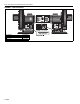
EP-300 SERIES PUMP INSTALLATION, OPERATION AND SERVICE MANUAL FIGURE 1: Label Placement Description Severe Injury Label Rating Plate Label Logo Label 2 of 33 Part Number 91012100 91010401 91017200
SECTION 2: INSTALLER RESPONSIBILITY SECTION 2: INSTALLER RESPONSIBILITY The installer is responsible for the following: • To install the pump and electrical supplies, in accordance with applicable specifications and codes. Roberts-Gordon recommends the installer contact a local building inspector or fire marshal for guidance. • To use the information given in a layout drawing and in the manual together with the cited codes and regulations to perform the installation.
EP-300 SERIES PUMP INSTALLATION, OPERATION AND SERVICE MANUAL SECTION 3: UNPACKING THE PUMP 3.1 Open Shipping Cartons WARNING Cut/Pinch Hazard Wear protective gear during installation, operation and service. Edges are sharp. Failure to follow these instructions can result in injury. Open cartons and remove packing inserts. Carefully remove pump components from the cartons. Lift assembly by gripping metal pump frame. Two people are required (weight 135 lbs, 61 kg).
SECTION 4: MAJOR COMPONENTS SECTION 4: MAJOR COMPONENTS FIGURE 2: Major Component Descriptions EP-301 Pump Assembly - 02730101 EP-303 Pump Assembly - 02730301 Pump Inlet Assembly - 90713454 Pump Scroll Assembly - 90713451 Pump Boot 4" (10 cm) - 91412800 Pump Boot 6" (15 cm) - 91412802 4" to 6" (10 cm x 15 cm) Adapter - 02719903 Band Clamp 4" (10 cm) - 91901300 Band Clamp 6" (15 cm) - 91913703 Pressure Switch - 90430600K Mounting Angle - 01365000 Bird Screen 6" (15 cm) - 01397400 5 of 33
EP-300 SERIES PUMP INSTALLATION, OPERATION AND SERVICE MANUAL 4.1 Standard Parts List Table 1: EP-301 Pump Package 4" (P/N 02723014) Part No.
SECTION 4: MAJOR COMPONENTS Table 2: EP-301 Pump Package 6" (P/N 02723016) Part No.
EP-300 SERIES PUMP INSTALLATION, OPERATION AND SERVICE MANUAL Table 3: EP-303 Pump Package 4" (P/N 02723034) Part No.
SECTION 4: MAJOR COMPONENTS Table 4: EP-303 Pump Package 6" (P/N 02723036) Part No.
EP-300 SERIES PUMP INSTALLATION, OPERATION AND SERVICE MANUAL SECTION 5: PUMP INSTALLATION WARNING at the bottom horizontal position. FIGURE 3: Pump Discharge Orientation Bottom Right Horizontal Discharge Severe Injury Hazard Secure pump to tube. Hang pump with materials with a minimum working load of 750 lbs (340 kg). Failure to follow these instructions can result in death, injury or property damage.
SECTION 5: PUMP INSTALLATION that adequate clearance is maintained between the impeller blades and the body of the pump scroll. 5.1.3 Attaching the Inlet Plate Assembly From the scroll assembly side of the pump, orient the inlet assembly so the threaded pipe coupling is on the top. See partial end view on Page 11, Figure 4. • Place inlet assembly onto the scroll assembly by fitting the inlet assembly onto the M8 screw studs on the scroll assembly. Be careful not to damage gasket.
EP-300 SERIES PUMP INSTALLATION, OPERATION AND SERVICE MANUAL FIGURE 5: Pump Impeller Rotation Counterclockwise Rotation Bottom Right Horizontal Discharge Position Clockwise Rotation Bottom Left Horizontal Discharge Position Arrow showing direction of rotation (located on the scroll housing) 5.2.1 Pump Inlet Adapter for 4" (10 cm) Tubing Apply a bead of silicone sealant (600° F) to the 6" (15 cm) inside of the adapter (6" x 4") (15 cm x 10 cm).
SECTION 5: PUMP INSTALLATION FIGURE 7: Pump Inlet Side 6" Band Clamp 6" (15 cm) CONNECT TO SYSTEM TUBING 6" (15 cm) Pump Boot 6" (15 cm) Inlet Assembly Description Pump Boot 6" (15 cm) Band Clamp 6" (15 cm) Inlet Assembly Part Number 91412802 91913703 90713451 5.2.3 Discharge Connection to 6" (15 cm) Flue Mount the 6" (15 cm) pump boot to the pump outlet using the 6" (15 cm) band clamp provided. See Page 13, Figure 8. FIGURE 8: Pump Discharge Side The minimum diameter outlet allowed is 6" (15 cm).
EP-300 SERIES PUMP INSTALLATION, OPERATION AND SERVICE MANUAL SECTION 6: PRESSURE SWITCH MOUNTING AND WIRING 6.1 Pressure Switch Installation 6.1.1 Attaching Pressure Switch to Pump Inlet For connection to a pump, locate the two pressure switch mounting holes on the pump frame. If replacing an old pressure switch, you may need to drill two holes in the pump frame (7/32" dia. approximately 13/16" apart).
SECTION 7: PUMP MOUNTING INSTRUCTIONS SECTION 7: PUMP MOUNTING INSTRUCTIONS 7.1 Mounting Platform The standard method of mounting the pump is on an outside wall and venting directly through the wall. The pump may be mounted by using mounting angles as shown in Figure 12 and Figure 13. The two mounting angles form a mounting platform to which the pump will be attached. Fix the mounting frame to the wall using anchors.
EP-300 SERIES PUMP INSTALLATION, OPERATION AND SERVICE MANUAL SECTION 8: MOTOR WIRING WARNING The power to the EP-301 pump is not supplied by the controller. Power is supplied by a separate circuit and is switched by the controller via a contactor with a 120 V AC coil. See Page 16, Figure 14. FIGURE 14: EP-301 Contactor Wiring Diagram Electrical Shock Hazard Disconnect electrical and gas before servicing. This appliance must be connected to a properly grounded electrical source.
SECTION 8: MOTOR WIRING FIGURE 15: Motor Wiring for EP-301 Pump (Clockwise Impeller Rotation) 8.3 EP-303 Wiring The EP-303 motor can be wired for 3 Ø, 208 V - 230 V/460 V, 60 Hz operation. Do not directly connect the controller relay terminals to the pump motor. Wires 1 and 5 to L1 Wire J When controlled by a system control, use Contactor Package 17A (P/N 10050011). See Page 17, Figure 16. See ROBERTS GORDON® System Control Manual (P/N 10091601NA) wiring details.
EP-300 SERIES PUMP INSTALLATION, OPERATION AND SERVICE MANUAL FIGURE 17: Motor Wiring for EP-303 (208 V - 230 V/460 V) 3 Ø Pump 208 V - 230 V 3 Ø 10 11 4 5 6 7 8 9 2 3 1 LINE 18 of 33 12 460 V 3 Ø Note: Interchange any two line leads to reverse rotation.
SECTION 9: VENTING SECTION 9: VENTING WARNING Carbon Monoxide Hazard Pump must be vented to the outside. Heaters must be installed according to the installation manual. Failure to follow these instructions can result in death or injury. WARNING 9.2 Venting the Pump • The exhaust connection from the pump is 6" (15 cm) diameter. • Connect the 6" (15 cm) pump boot (provided) to the 6" (15 cm) flue pipe, using the 6" (15 cm) band clamp provided.
EP-300 SERIES PUMP INSTALLATION, OPERATION AND SERVICE MANUAL • Locate vent terminal at least 12" (30 cm) from any opening through which vent gases could enter a building. • Use only corrosion resistant materials for the discharge line from the pump to the point of discharge. • Vent terminal opening must extend beyond any combustible overhang. • Install vent terminal at a height sufficient to prevent blockage by snow. • Protect building materials from degradation by flue gases.
SECTION 9: VENTING FIGURE 19: Vertical Venting Description Tee 6" (15 cm) Vent Cap 6" (15 cm) Drain Cap 6" (15 cm) Part Number 01330204 90502302 02718852 9.7 Condensate Tee Assembly The condensate tee assembly is composed of a tee, draincap, and condensate trap. If the system is designed in the condensing mode, then the installation of a condensate tee assembly is required.
EP-300 SERIES PUMP INSTALLATION, OPERATION AND SERVICE MANUAL FIGURE 20: Condensate Tee Assembly at Pump Inlet System Tailpipe Tee Wall Description Tee 4" (10 cm) Tee 6" (15 cm) Drain Cap 4" (10 cm) Drain Cap 6" (15 cm) Condensate Valve Assembly Drain Cap 1" NPT threaded hole. Use 1" x ¾" reducer (Not supplied.) Copper or galvanized pipe between pump and condensate valve. 36" (.9 m) Minimum vertical drop between pump and condensate valve assembly.
SECTION 9: VENTING FIGURE 22: Condensate Check Valve Description Condensate Valve Assembly Part Number 01327001 FIGURE 23: Condensate Tee - Discharge Side 9.8 Condensate Trap and Condensate Tee The condensate trap assembly (optional) (P/N 01327001), should be installed on the inlet side of the pump assembly, See Page 23, Figure 22. It is possible to eliminate the condensate trap assembly on the pump if the one-inch threaded hole is plugged.
EP-300 SERIES PUMP INSTALLATION, OPERATION AND SERVICE MANUAL Step 1: Condensate flow (gal/h) per 100,000 Btu/h installed You will need to know the tailpipe length per flow unit and the total input (Btu/h) on the heating system. Please refer to the following chart to determine the condensate flow (gal/h) per 100,000 Btu/h installed: Radiant Tube Length (average distance between burners) Minimum Recommended Maximum Tailpipe Length per Flow Unit Minimum Recommended N/A 0.1 0.3 0.1 0.3 0.6 1.
SECTION 9: VENTING FIGURE 24: Condensate Neutralization Tube Calculated gal/h Less than 2 Less than 6 Less than 10 Less than 20 Description Part Number Condensate Neutralization Tube 200 01327002 Condensate Neutralization Tube 600 01327003 Condensate Neutralization Tube 1000 01327004 Condensate Neutralization Tube 2000 01327005 25 of 33
EP-300 SERIES PUMP INSTALLATION, OPERATION AND SERVICE MANUAL SECTION 10: SERVICING INSTRUCTIONS WARNING DANGER Electrical Shock Hazard Disconnect electric before service. Explosion Hazard Turn off gas supply to heater before service. Heater and pump must be connected to a properly grounded electrical source. Burn Hazard Allow heater and pump to cool before service. Cut/Pinch Hazard Wear protective gear during installation, operation and service. Tubing may still be hot Edges are sharp.
SECTION 10: SERVICING INSTRUCTIONS from the end of the motor shaft. With an appropriate wheel puller, remove the impeller. 6. The motor can now be removed, if necessary, by removing the attachment hardware. 7. Re-assembly of motor/impeller combination requires proper alignment. Be certain of proper motor alignment and free rotation. 8. The four set screws should be reinstalled with a drop of thread locking sealant and remain unseated during initial re-assembly. 9.
EP-300 SERIES PUMP INSTALLATION, OPERATION AND SERVICE MANUAL 10.3 Maintenance Checklist and safety, Roberts-Gordon LLC recommends that a qualified contractor conduct, at a minimum, annual inspections of your ROBERTS GORDON® equipment and perform service where necessary, using only replacement parts sold and supplies by RobertsGordon LLC.
SECTION 11: REPLACEMENT PARTS AND ACCESSORIES SECTION 11: REPLACEMENT PARTS AND ACCESSORIES WARNING DANGER Electrical Shock Hazard Explosion Hazard Fire Hazard Carbon Monoxide Hazard Use only genuine ROBERTS GORDON® replacement parts per this installation, operation and service manual. Failure to follow these instructions can result in death, electric shock, injury or property damage. .
EP-300 SERIES PUMP INSTALLATION, OPERATION AND SERVICE MANUAL Description 4" Damper Coupling 6" Damper Coupling 4" Aluminized Tee 6" Aluminized Tee 4" Coated Tee 4" Aluminized Cross 30 of 33 Part Number 01331900 E0009356 01330203 01330204 0133022D 01330903 Description 6" Aluminized Cross 4" Coated Cross 4" Aluminized 90° Elbow 6" Aluminized 90° Elbow 4" Coated 90° Elbow Part Number 01330904 0133092D 01335801 T0100320 0133580D
SECTION 12: SPECIFICATIONS SECTION 12: SPECIFICATIONS 12.1 Material Specifications 12.1.1 Pump Frame, Inlet, Scroll and Impeller 3 mm welded steel construction 12.1.2 Pump Weight 12.3 EP-303 Controls Specifications Motor starters are sold separately. When using a System Control, use Starter Package P/N 10050010. With ROBERTS GORDON® ULTRAVAC™, use variable frequency drive (P/N VFD20230), sold separately. 170 lbs (78 kg) 12.
EP-300 SERIES PUMP INSTALLATION, OPERATION AND SERVICE MANUAL 32 of 33
SECTION 13: THE ROBERTS GORDON® EP-300 SERIES PUMP WARRANTY SECTION 13: THE ROBERTS GORDON® EP-300 SERIES PUMP WARRANTY ROBERTS-GORDON LLC WILL PAY FOR: Within 36 months from date of purchase by buyer or 42 months from date of shipment by Roberts-Gordon LLC (whichever occurs first), replacement parts will be provided free of charge for any part of the product which fails due to a manufacturing or material defect. Roberts-Gordon LLC will require the part in question to be returned to the factory.