EP-300 Series Installation, Operation & Service Manual WARNING Improper installation, adjustment, alteration, service or maintenance can result in death, injury or property damage. Read the installation, operation and service manual thoroughly before installing or servicing this equipment. Installation must be done by a contractor qualified in the installation and service of gas-fired heating equipment or your gas supplier.
TABLE OF CONTENTS SECTION 1: Heating System Safety ............................1 1.1 Manpower Requirements ...................................1 SECTION 2: Installer Responsibility............................2 2.1 Corrosive Chemicals...........................................2 2.2 National Standards and Applicable Codes .........2 SECTION 3: Unpacking the Pump ...............................2 3.1 Open Shipping Cartons ......................................2 SECTION 4: Major Components .......................
TABLE OF FIGURES Figure 1: Major Component Descriptions .......................3 Figure 2: Pump Discharge Orientation............................8 Figure 3: Installation Configurations................................9 Figure 4: Pump Impeller Rotation ...................................9 Figure 5: Wall Bracket Assembly ..................................10 Figure 6: Mounting Platform Options ............................10 Figure 7: Pump Inlet Side 4" .........................................
SECTION 1: HEATING SYSTEM SAFETY SECTION 1: HEATING SYSTEM SAFETY Your Safety is Important to Us! This symbol is used throughout the manual to notify you of possible fire, electrical or burn hazards. Please pay special attention when reading and following the warnings in these sections. Installation, Service and Annual Inspection of heater and pump must be done by a contractor qualified in the installation and service of gas-fired heating equipment.
EP-300 SERIES PUMP INSTALLATION, OPERATION AND SERVICE MANUAL SECTION 2: INSTALLER RESPONSIBILITY The installer is responsible for the following: • To install the pump and electrical supplies, in accordance with applicable specifications and codes. Roberts-Gordon recommends the installer contact a local building inspector or Fire Marshal for guidance. • To use the information given in a layout drawing and in the manual together with the cited codes and regulations to perform the installation. 2.
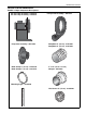
SECTION 4: MAJOR COMPONENTS SECTION 4: MAJOR COMPONENTS FIGURE 1: Major Component Descriptions EP-301 Pump Assembly - 02730101 EP-303 Pump Assembly - 02730301 Pump Scroll Assembly - 90713451 Pump Inlet Assembly - 90713454 Pump Boot 4" (10 cm) - 91412800 Pump Boot 6" (15 cm) - 91412802 Band Clamp 4" (10 cm) - 91901300 Band Clamp 6" (15 cm) - 91913703 4" to 6" (10 cm x 15 cm) Adapter - 02719903 Mounting Angle - 01365000 Bird Screen 6" (15 cm) - 01397400 3
EP-300 SERIES PUMP INSTALLATION, OPERATION AND SERVICE MANUAL 4.1 Standard Parts List Table 1: EP-301 Pump Package 4" (P/N 02723014) Part No.
SECTION 4: MAJOR COMPONENTS Table 2: EP-301 Pump Package 6" (P/N 02723016) Part No.
EP-300 SERIES PUMP INSTALLATION, OPERATION AND SERVICE MANUAL Table 3: EP-303 Pump Package 4" (P/N 02723034) Part No.
SECTION 4: MAJOR COMPONENTS Table 4: EP-303 Pump Package 6" (P/N 02723036) Part No.
EP-300 SERIES PUMP INSTALLATION, OPERATION AND SERVICE MANUAL SECTION 5: PUMP INSTALLATION 5.1 Pump Assembly Instructions 5.1.1 Determine Orientation of Pump Discharge To ensure your safety, and comply with the terms of the warranty, all units must be installed in accordance with these instructions. The pump must be installed in a location that it is readily accessible for servicing. Pump discharge orientation is viewed from the rear of the motor as shown in on Page 8, Figure 2.
SECTION 5: PUMP INSTALLATION FIGURE 3: Installation Configurations Side View M8 Hexnut and Washer Partial End View Inlet Assembly Vertical Scroll Assembly Mounting M8 Screw Plate Stud Pressure Switch Threaded Pipe Coupling Impeller M8 Hexnut and Washer Description Pressure Switch Pump Scroll Hex Nut, M8 (24) Washer, M8 x 16 OD x 1.6 Impeller Part Number 90430600 90713451 92204502 95204502 90713340 orientation is bottom right horizontal.
EP-300 SERIES PUMP INSTALLATION, OPERATION AND SERVICE MANUAL 5.3 Mounting Wall Bracket Assembly 5.3.1 Mounting Platform WARNING The standard method of mounting the pump is on an outside wall and venting directly through the wall. Suspension Hazard Mount pump with materials with a minimum working load of 400 lbs (181 kg). The pump may be mounted by using mounting angles as shown in Figure 5 and Figure 6. The two mounting angles form a mounting platform to which the pump will be attached.
SECTION 5: PUMP INSTALLATION 5.3.2 Attaching Pressure Switch to Pump Inlet FIGURE 8: Pump Inlet Side 6" Apply silicone sealant (600° F) to the threads of the pressure switch and then screw the pressure switch into the 1/8" NPT hole provided on the pump inlet. See Page 9, Figure 3. Care must be taken to make certain that the application of silicone does not plug the orifice hole of the pressure switch. Without pump verification, the system will not operate.
EP-300 SERIES PUMP INSTALLATION, OPERATION AND SERVICE MANUAL 5.4 Condensate Tee Assembly The condensate tee assembly is composed of a tee, draincap, and condensate trap. If the system is designed in the condensing mode, then the installation of a condensate tee assembly is required. The condensate tee assembly, must be installed on the inlet side of the pump assembly if there is horizontal venting of the pump, See Page 12, Figure 10.
SECTION 5: PUMP INSTALLATION FIGURE 11: Condensate Drain for Vertical Venting Roof Tee 6" (15 cm) Flue 6" (15 cm) Minimum Pump Discharge Description Tee 6" (15 cm) Drain Cap 6" (15 cm) Drain Cap 6" (15 cm) to drain Part Number 01330204 02718852 13
EP-300 SERIES PUMP INSTALLATION, OPERATION AND SERVICE MANUAL SECTION 6: MOTOR WIRING WARNING Electrical Shock Hazard Disconnect electrical power and gas supply before servicing. This appliance must be connected to a properly grounded electrical source. Failure to follow these instructions can result in death or electrical shock. All wiring must comply with current wiring regulations and any local regulations which may apply. Always switch off the supply and disconnect before servicing.
SECTION 6: MOTOR WIRING Wire the pressure switch per the appropriate wiring diagram in the Controller Installation Manual. 6.3 EP-303 Wiring The EP-303 motor can be wired for 3 Ø, 208 V - 230 V/460 V, 60 Hz operation. Do not directly connect the controller relay terminals to the pump motor. When controlled by a System Control or BZC 700, use starter package P/N 10050010. See Page 15, Figure 14. See Controller Installation Manual for (P/N 10091601NA) wiring details.
EP-300 SERIES PUMP INSTALLATION, OPERATION AND SERVICE MANUAL 7.3 Horizontal Venting SECTION 7: VENTING WARNING Carbon Monoxide Hazard Pump must be vented to the outside. Heaters must be installed according to the installation manual. Failure to follow these instructions can result in death or injury. 7.1 General Venting Requirements Install the venting in accordance with the requirements within this manual and the National Fuel Gas Code, ANSI Z223.1/NFPA-54 - latest revision and CSA 22.
SECTION 7: VENTING FIGURE 16: Horizontal Venting NOTE: See Page 21, Section 9 for common venting components and part numbers. 10' (3 m) Maximum and 1 Elbow 18" (46 cm) Minimum 40" (102 cm) Maximum 10' (3 m) Maximum and 1 Elbow Single Wall Pipe/Tube 6" (15 cm) Pitch single wall pipe downward away from pump 1/4" every 10' (3 m). Thimble (Not required on non-combustible walls.
EP-300 SERIES PUMP INSTALLATION, OPERATION AND SERVICE MANUAL 7.4 Vertical Venting The vent material must be either heat treated aluminized tubing 6" (15 cm) O.D. (P/N E0009105) or single wall flue pipe minimum 26 Ga.). Vent length should be limited to less than 20' (6 m). If using vent lengths greater than 20' (6 m), condensation will form in the vent pipe. Insulation and additional sealing measures will be required. Length of flue pipe is equal to total of vertical and horizontal length. 7.
SECTION 8: SERVICING INSTRUCTIONS SECTION 8: SERVICING INSTRUCTIONS WARNING some of the areas requiring inspection. Please see Page 20, Section 8.3 for suggested items to inspect. Severe Injury Hazard Install pump scroll and inlet assembly before operating high speed rotating impeller. 8.2 To Change the Motor and/or the Impeller Keep hands, fingers and clothing away from inlet and outlet.
EP-300 SERIES PUMP INSTALLATION, OPERATION AND SERVICE MANUAL 8.3 Maintenance Checklist Installation, Service and Annual Inspection of the pump must be done by a contractor qualified in the installation and service of gas-fired heating equipment. Turn off the system and ensure power and gas supply is shut off before servicing equipment. Read this manual carefully before installation, operation, or service of this equipment. System Tubing and Vent Pipe Venting must be intact.
SECTION 9: REPLACEMENT PARTS AND ACCESSORIES SECTION 9: REPLACEMENT PARTS AND ACCESSORIES Use only genuine ROBERTS GORDON® replacement parts. Use of parts not specified by Roberts-Gordon voids warranty. Failure to follow these instructions can result in property damage. Pressure Switch Motor Band Clamp 4" or 6" (10 or 15 cm) Adapter 4" to 6" (10 to15 cm) for 4" (10 cm) tailpipe only Band Clamp 6" (15 cm) Pump Boot 4" or 6" (10 or 15 cm) Pump Boot 6" (15 cm) 9.
EP-300 SERIES PUMP INSTALLATION, OPERATION AND SERVICE MANUAL SECTION 10: SPECIFICATIONS 10.1 Material Specification 10.1.1 Pump Frame, Inlet, Scroll and Impeller 3 mm welded steel construction 10.3 Suspension Specifications 10.4 EP-301 Controls Specifications 10.1.2 Pump Weight Motor controls and contactors are sold separately. Use contactor package P/N 10050009. 135 lbs (61 kg) 10.5 EP-303 Controls Specifications 10.
SECTION 11: THE ROBERTS GORDON® EP-300 SERIES PUMP LIMITED WARRANTY SECTION 11: THE ROBERTS GORDON® EP-300 SERIES PUMP LIMITED WARRANTY ROBERTS-GORDON WILL PAY FOR: ROBERTS GORDON® warrants to the original owneruser that this ROBERTS GORDON® product will be free from defects in material and workmanship. This warranty is limited to thirty-six (36) months from the date of purchase by the original consumer, or forty-two (42) months from date of shipment by Roberts-Gordon, whichever occurs first.