System Control Installation, Operation & Service Manual Installer WARNING Improper installation, adjustment, alteration, service or maintenance can result in death, injury or property damage. Read the Installation, Operation and Service Manual thoroughly before installing or servicing this equipment. Installation must be done by a contractor qualified in the installation and service of gas-fired heating equipment or your gas supplier.
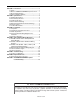
TABLE OF CONTENTS SECTION 1: Introduction........................................................ 1 1.1 Safety ........................................................................... 1 1.2 What is a ROBERTS GORDON® System Control? ...... 1 1.3 Electrical Requirements ............................................... 1 1.4 Check Installation Materials ......................................... 1 SECTION 2: Specifications .................................................... 3 2.1 Material Specifications ....
TABLE OF FIGURES Figure 1: Panel Layout .............................................................. 3 Figure 2: Terminal Block Guide ................................................. 4 Figure 3: Mounting Hole Layout................................................ 5 Figure 4: System Configuration ................................................. 6 Figure 5: External Wiring Diagram ROBERTS GORDON® EP-100 and EP-201 120 V 1 Ø Pump ......................
SECTION 1: INTRODUCTION SECTION 1: INTRODUCTION 1.1 Safety Your Safety is Important to Us! This 1.3 Electrical Requirements symbol is used throughout the manual to notify you of possible fire, electrical or burn hazards. Please pay special attention when reading and following the warnings. DANGER Installation, service and annual inspection of controller must be done by an electrician qualified in the installation and service of control systems for heating equipment.
SYSTEM CONTROL INSTALLATION, OPERATION AND SERVICE MANUAL 1.4.2 Electrical Installation Materials 120 V, 60 Hz, 1 Ø, 20 A, power supply to the control panel must be installed in accordance with the most current National Electrical Code®, local codes and any site specific diagrams. Total load powered by the panel must not exceed 20 A. Loads totaling more than 20 A must be powered from an additional power supply circuit by the use of a load relay package. 1.4.
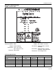
SECTION 2: SPECIFICATIONS SECTION 2: SPECIFICATIONS FIGURE 1: Panel Layout 2.2 Electrical Specifications 2.1 Material Specifications Supply: 120 V, 60 Hz, 1 Ø, 20 A Enclosure Material: Metal Zone Relay: Single pole 20 A, 120 Vac (resistive) Weight: 6.8 lbs (3.08 kg) Dimensions: 10.2" x 11.4" x 2.8" (25.4 x 29.0 x 7.1 cm) Pump Relay: Single pole 20 A, 120 Vac (resistive) 1 HP motor rated. Protection: Rating IP20 Thermostats: Low voltage 24 Vac 2.
SYSTEM CONTROL INSTALLATION, OPERATION AND SERVICE MANUAL 2.4 Burner Electrical Ratings CORAYVAC® burners: 120 V, 60 Hz, 1 Ø 0.3 A VANTAGE® NP (multiburner only) burners:120 V, 60 Hz, 1 Ø 0.2 A 2.5 Outside Air Supply Blower Electrical Ratings Outside air supply blower (P/N 90707501K) has a full load rating of 1.6 A when supplied by a 120 V, 60 Hz, 1 Ø power source. 2.6 Indicator Lights See Page 3, Figure 1. 1. LINE POWER, when lit, indicates power is supplied to the panel. 2.
SECTION 3: INSTALLATION SECTION 3: INSTALLATION DANGER Electrical Shock Hazard Disconnect electric before service. Controller must be properly grounded to an electrical source. 3.2.6 When the case is rotated 180°, the LED status circuit card needs to be rotated so that the LED's match the upright cover panel. Remove the LED status circuit card by squeezing each standoff gently with pliers one at a time until it is loose.
SYSTEM CONTROL INSTALLATION, OPERATION AND SERVICE MANUAL • Pressure Switch Input The wiring connection for pressure switch should be unshielded 18 AWG wire. • Thermostats The wiring connection for Thermostats should be unshielded cable, and recommend for wire gauges as indicated on on Page 13, Section 4.5 3.4 Select the External Wiring Diagram for the Installation 3.4.1 Use Page 7, Section 4 for the external wiring of the burners, thermostats and pressure switch. 3.4.
SECTION 4: TYPICAL EXTERNAL WIRING DIAGRAMS SECTION 4: TYPICAL EXTERNAL WIRING DIAGRAMS DANGER burners can be either CORAYVAC® or VANTAGE® NP (multiburner only). The zones are connected to a single pump, unless zone 3 and/or zone 4 are selected to function with the optional pump 2. The external wiring diagram below shows connection to an EP-100 or EP-201 120 V 1 Ø pump. 4.1.1 External Wiring Connection Details Electrical Shock Hazard Disconnect electric before service.
SYSTEM CONTROL INSTALLATION, OPERATION AND SERVICE MANUAL FIGURE 6: External Wiring Diagram ROBERTS GORDON® EP-100, EP-201 or EP-301, 230 V 1 Ø Pump CAUTION EP-100, EP-201 or EP-301 Pump Product Damage Hazard Motor Contactors P/N 10050011 P/N 10050012 Do not directly connect control relay terminals to pump motor. Failure to follow these instructions can result in product damage.
SECTION 4: TYPICAL EXTERNAL WIRING DIAGRAMS ration of circuit requirements. National Electrical Codes® for wiring class 2 low voltage circuits must be followed. As per individual building specification for class of cable to be used. Use copper conductors only.
SYSTEM CONTROL INSTALLATION, OPERATION AND SERVICE MANUAL FIGURE 7: External Wiring Diagram ROBERTS GORDON® EP-203 or EP-303, 208 - 230 V (or 460 V) 3 Ø Pump CAUTION Product Damage Hazard Do not directly connect control relay terminals to pump motor. EP-203 or EP- 303 3 Ø Pump Motor Contactors P/N 10050011 P/N 10050012 Failure to follow these instructions can result in product damage.
SECTION 4: TYPICAL EXTERNAL WIRING DIAGRAMS The low voltage circuits conforms with Class 2 separation of circuit requirements. National Electrical Codes® for wiring class 2 low voltage circuits must be followed. As per individual building specification for class of cable to be used. Use copper conductors only.
SYSTEM CONTROL INSTALLATION, OPERATION AND SERVICE MANUAL FIGURE 8: External Wiring Diagram ROBERTS GORDON® EP-100 or EP-201 120 V 1 Ø Pump with Outside Air Blower Note: For applications requiring zones to share thermostats, see Page 13, Section 4.6 *Without blower contacts need to be n/c. 4.4 Outside Air Blower External Wiring Diagram The external wiring diagram above shows the con12 of 19 nections for four zones of system burners.
SECTION 4: TYPICAL EXTERNAL WIRING DIAGRAMS The zones are connected to a single pump, unless zone 3 and/or zone 4 are selected to function with the optional pump 2. The external wiring diagram above shows connection to an EP-100 or EP-201 1 Ø motor. The diagram also shows the connection via a load relay to the optional outside air blower. 4.4.1 External Wiring Connection Details Low voltage wiring (pressure switch, thermostats) must be rated to 300 V. Line voltage wiring must be rated to 600 V.
SYSTEM CONTROL INSTALLATION, OPERATION AND SERVICE MANUAL SECTION 5: TROUBLESHOOTING DANGER Electrical Shock Hazard Disconnect electric before service. More than one disconnect switch may be required to disconnect electric to the unit. Failure to follow these instructions can result in death or electrical shock. WARNING Explosion Hazard Turn off gas supply to heater before service. Failure to follow these instructions can result in death, injury or property damage. 5.1 Sequence of Operation a.
SECTION 5: TROUBLESHOOTING FIGURE 9: System Control Troubleshooting Chart If control is not working properly, disconnect power to control and check for signs of physical damage to the front and back of the circuit board, water damage (corrosion) or scorching. If damage is found, identify and rectify source of damage. Replace circuit board (P/N 10090101), if it has permanent damage.
SYSTEM CONTROL INSTALLATION, OPERATION AND SERVICE MANUAL SECTION 6: REPLACEMENT PARTS WARNING DANGER Electrical Shock Hazard Explosion Hazard Fire Hazard Carbon Monoxide Hazard Use only genuine ROBERTS GORDON® replacement parts per this installation, operation and service manual. Failure to follow these instructions can result in death, electric shock, injury or property damage.
SECTION 6: REPLACEMENT PARTS 6.1 Replacement Parts Instructions DANGER Electrical Shock Hazard Disconnect electric before service. More than one disconnect switch may be required to disconnect electric to the unit. Failure to follow these instructions can result in death or electrical shock. 6.1.1 Transformer The transformer on the board cannot be replaced. See Page 16, Figure 10, Item 1. 6.1.2 Microprocessor Programing The microprocessor may be re-programed by a reprograming device.
SYSTEM CONTROL INSTALLATION, OPERATION AND SERVICE MANUAL 18 of 19
SECTION 7: THE ROBERTS GORDON® SYSTEM CONTROL WARRANTY SECTION 7: THE ROBERTS GORDON® SYSTEM CONTROL WARRANTY ROBERTS-GORDON LLC WILL PAY FOR: Within 36 months from date of purchase by buyer or 42 months from date of shipment by Roberts-Gordon LLC (whichever occurs first), replacement parts will be provided free of charge for any part of the product which fails due to a manufacturing or material defect. Roberts-Gordon LLC will require the part in question to be returned to the factory.