FOR YOUR SAFETY If you smell gas: 1. Open windows. 2. DO NOT try to light any appliance. 3. DO NOT use electrical switches. 4. DO NOT use any telephone in your building. 5. Extinguish any open flame. 6. Leave the building. 7. Immediately call your local gas supplier after leaving the building. Follow the gas supplier’s instructions. 8. If you cannot reach your gas supplier, call the Fire Department.
POUR VOTRE SECURITE Si vous sentez une odeur de gaz: 1. Ouvrez les fenêtres. 2. N’essayez PAS d’allumer un appareil. 3. N’utilisez PAS d’interrupteurs électriques. 4. N’utilisez PAS de téléphone dans votre bâtiment. 5. Eteignez toute flamme nue. 6. Quittez le bâtiment. 7. Après avoir quitté le bâtiment, appelez immédiatement votre fournisseur local de gaz. Suivez les instructions du fournisseur de gaz. 8. Si vous ne pouvez pas joindre votre fournisseur de gaz, appelez le service d’incendie.
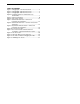
TABLE OF CONTENTS SECTION 1: Heater Safety...................................................... 1 1.1 Manpower Requirements ............................................. 1 1.2 Safety Labels and Their Placement ............................. 1 1.3 California Proposition 65 .............................................. 1 2.1 Wall Tag ....................................................................... 5 2.2 Corrosive Chemicals.................................................... 5 2.
TABLE OF FIGURES Figure 1: UHA[X][S]150 - 175 Label Placement........................ 2 Figure 2: UHA[X][S]200 - 250 Label Placement ....................... 3 Figure 3: UHA[X][S]300 - 400 Label Placement ....................... 4 Figure 4: Installation Clearances and Clearances to Combustibles............................................................. 7 Figure 5: Suspension Methods ............................................... 10 Figure 6: Vent and Roof Detail ...........................................
SECTION 1: HEATER SAFETY SECTION 1: HEATER SAFETY Your Safety is Important to Us! This symbol is used throughout the manual to notify you of possible fire, electrical or burn hazards. Please pay special attention when reading and following the warnings in these sections. Installation, service and, at a minimum, annual inspection of heater must be done by a contractor qualified in the installation and service of gas-fired heating equipment.
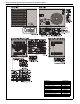
UHA STANDARD UNIT HEATER INSTALLATION OPERATION AND SERVICE MANUAL Figure 1: UHA[X][S]150 - 175 Label Placement Description Logo Label Cut Hazard Label Vent Length Label Vent to Outdoors Label Warning Label Rating Plate Label Installation Label Instruction Location Label Lighting Instruction Label Venting Arrangement Label* Proposition 65 Label Part Number 91040030 91010430 91039505 91010427 91010429 91010419 91010431 91010433 91010425 91010426 91070015 *For separated combustion units only.
SECTION 1: HEATER SAFETY Figure 2: UHA[X][S]200 - 250 Label Placement Description Logo Label Cut Hazard Label Vent Length Label Vent to Outdoors Label Warning Label Rating Plate Label Installation Label Instruction Location Label Lighting Instruction Label Venting Arrangement Label* Proposition 65 Label Part Number 91040030 91010430 91039505 91010427 91010429 91010419 91010431 91010433 91010425 91010426 91070015 *For separated combustion units only.
UHA STANDARD UNIT HEATER INSTALLATION OPERATION AND SERVICE MANUAL Figure 3: UHA[X][S]300 - 400 Label Placement Description Logo Label Cut Hazard Label Vent Length Label Vent to Outdoors Label Warning Label Rating Plate Label Installation Label Instruction Location Label Lighting Instruction Label Venting Arrangement Label* Proposition 65 Label Part Number 91040030 91010430 91039505 91010427 91010429 91010419 91010431 91010433 91010425 91010426 91070015 *For separated combustion units only.
SECTION 1: HEATER SAFETY SECTION 2: INSTALLER RESPONSIBILITY The installer is responsible for the following: • To install the heater, as well as the gas and electrical supplies, in accordance with applicable specifications and codes. Roberts-Gordon LLC recommends the installer contact a Local Building Inspector or Fire Marshal for guidance. • To use the information given in a layout drawing and in the manual together with the cited codes and regulations to perform the installation. 2.
UHA STANDARD UNIT HEATER INSTALLATION OPERATION AND SERVICE MANUAL SECTION 3: CRITICAL CONSIDERATIONS 3.1 Basic Information UHA[X][S] heaters have automatic ignition burners for ON/OFF operation only. 3.2 Manufactured Units Gas-fired, power-vented unit heater with tubular heat exchanger. Units shall have a minimum of 82% thermal efficiency. The standard unit shall consist of a non-separated combustion design with an aluminized heat exchanger.
SECTION 4: CLEARANCES TO COMBUSTIBLES SECTION 4: CLEARANCES TO COMBUSTIBLES 4.1 Required Clearances To Combustibles WARNING Fire Hazard Clearances for all heater models are located on the serial plate of the heater and throughout the manual. Check the clearances on the serial plate to make sure the product is suitable for your application and the clearances are maintained.
UHA STANDARD UNIT HEATER INSTALLATION OPERATION AND SERVICE MANUAL SECTION 5: NATIONAL STANDARDS AND APPLICABLE CODES 5.1 Gas Codes The type of gas appearing on the name plate must be the type of gas used. Installation must comply with national and local codes and requirements of the local gas company. United States: Refer to NFPA 54/ANSI Z223.1 latest revision, National Fuel Gas Code. Canada: Refer to CSA B149.1 Natural Gas and Propane Installation Code. 5.
SECTION 5: NATIONAL STANDARDS AND APPLICABLE CODES 5.6 High Altitude These heaters are approved (without modifications) for installations up to 2000' (610 m) in US and Canada. Heaters installed above 2000' (610 m) must be de-rated. For installations above 2000' (610 m) in US, consult factory for information on burner de-rating. For installations from 2000' (610 m) to 4500' (1370m) in Canada, high altitude conversion kits are available.
UHA STANDARD UNIT HEATER INSTALLATION OPERATION AND SERVICE MANUAL SECTION 6: HEATER INSTALLATION 6.1 General Heaters are designed for installation above 6' (1.8 m). These heaters must be installed within the heated space. Duct delivery systems are not permitted with axial fan units. When handling or supporting the heater from below, ensure that the weight is taken at the support points. The gas or electrical supply lines must not be used to support the heater.
SECTION 7: VENTING SECTION 7: VENTING WARNING 100-73 standards. High temperature silicone sealant must have a minimum temperature rating of 480° F (250° C). Carbon Monoxide Hazard Heaters may be installed vented or unvented. Vented heaters must be vented outdoors. Unvented heaters must be installed according to the installation manual. Failure to follow these instructions can result in death or injury. 7.
UHA STANDARD UNIT HEATER INSTALLATION OPERATION AND SERVICE MANUAL 7.2.1 Standard Vented Heaters (Models UHA[X] 150 - 400) The vent must be fitted with a low resistance terminal. See Page 13, Figure 6 through Page 14, Figure 7. Standard vented heaters do not allow outdoor air intake for combustion air. 7.2.2 Separated Combustion Heaters (Models UHA[X]S 150 - 400) The heaters are designed to be installed as separated combustion heaters.
SECTION 7: VENTING Maximum Vent Lengths Table Model UHA[X][S] 150 - 400 40 ft (12.2 m) 35 ft (10.7 m) 30 ft (9.1 m) 25 ft (7.6 m) 20 ft (6.1 m) # of Elbows 1 2 3 4 5 7.7 Vent Material Vent material may be single wall 26 ga. (minimum) galvanized steel or equal thickness stainless steel. Completely seal all joints, refer to Page 11, Section 7.2. If penetrating a combustible wall or roof, a listed thimble with 2" (5 cm) clearance must be used.
UHA STANDARD UNIT HEATER INSTALLATION OPERATION AND SERVICE MANUAL Figure 7: Standard Vented Heater - Vertical and Horizontal Vent Termination Vent Terminal Flashing (By Others) Listed Thimble (2" [5cm] Clearance) 4" (10cm) Diameter Vent Vertical Option 90° Bend Horizontal Option Listed Thimble (2" [5cm] Clearance) Flashing (By Others) Vent Terminal Vent 12" (31 cm) Minimum Model UHA[X] 150 - 400 14 of 51 Vent Diameter 4" (10 cm) Part Number 90502102 NOTE: Vent supports not shown.
SECTION 7: VENTING Figure 8: Standard Vented Heater - Common Vertical Vent Termination Requirements: • Maximum of four heaters can be commonly vented through the roof. • Heaters must be of the same BTU output. • Heaters must be controlled by a common thermostat, • Connections to a common stack must be positioned to avoid direct opposition between streams of combustion gases.
UHA STANDARD UNIT HEATER INSTALLATION OPERATION AND SERVICE MANUAL Figure 9: Separated Combustion Heater - Vertical and Horizontal Vent Termination 12" (31 cm) Minimum from air inlet to vent termination. 12" (31 cm) Minimum from roof to vent termination. Vent** Air Intake* Vertical Option Horizontal Option 90° Bend Air Intake 12" (31 cm) Minimum from air inlet to vent termination. Air Intake Termination Vent Termination Vent** 12" (31 cm) Minimum from wall to vent termination.
SECTION 7: VENTING Figure 11: Concentric Vertical and Horizontal Vent Termination - Separated Combustion Heater 4" (10 cm) Type B-1Vent Vent Terminal with Baffle Plate UHAS 150-250: 6" (15 cm) Diameter Single Wall UHAS 300-400: 8" (20 cm) Diameter Single Wall 6" (16 cm) Minimum 12" (31 cm) Maximum Storm Collar (By Others) (Attach with 3 sheet metal screws.
UHA STANDARD UNIT HEATER INSTALLATION OPERATION AND SERVICE MANUAL SECTION 8: AIR SUPPLY WARNING Explosion Hazard Equipment must have access to uncontaminated air at all times. Failure to follow these instructions can result in death, injury or property damage. 8.1 Separated Combustion Installation When installed as a separated combustion heater (UHA[X]S), the air for combustion is drawn in from outside the building.
SECTION 9: GAS PIPING SECTION 9: GAS PIPING Canada: Rubber type 1 gas hose (Canadian models) is certified as being in compliance with the standard for elastomeric composite hose and hose couplings for conducting propane and natural gas, CAN/CGA 8.1 - latest revision. WARNING Explosion Hazard Leak test all components of gas piping before operation. Gas can leak if piping is not installed properly. Do not high pressure test gas piping with heater connected.
UHA STANDARD UNIT HEATER INSTALLATION OPERATION AND SERVICE MANUAL Figure 12: Gas Connection CAUTION Product Damage Hazard Hold gas nipple securely with pipe wrench when attaching flexible gas connector. Failure to follow these instructions can result in product damage. • Hold gas nipple securely with pipe wrench when attaching the flexible gas connector. Option A: Stainless Steel Flexible Gas Connector Do not bend flexible gas connector • Do not twist flexible gas connector.
SECTION 10: WIRING Heater must be wired and electrically grounded in accordance with local codes. In the absence of local codes in accordance with: United States: refer to National Electrical Code® NFPA 70 - latest revision Canada: refer to Canadian Electrical Code CSA C22.1 Part I - latest revision. SECTION 10: WIRING DANGER Electrical Shock Hazard Disconnect electric before service. More than one disconnect switch may be required to disconnect electric from equipment.
UHA STANDARD UNIT HEATER INSTALLATION OPERATION AND SERVICE MANUAL 10.3 Low Voltage Thermostat with Multiple Heaters (Models UHA[X][S]150 - 250) Model UHA[X][S]150 - 250 22 of 51 Relay Type DPST Relay Part Number 90436300 Max.
SECTION 10: WIRING 10.4 Low Voltage Thermostat with Multiple Heaters (Models UHA[X][S]300 - 400) Model UHA[X][S]300 - 400 Relay Type DPST Relay Part Number 90436300 Max.
UHA STANDARD UNIT HEATER INSTALLATION OPERATION AND SERVICE MANUAL 10.
SECTION 10: WIRING 10.
UHA STANDARD UNIT HEATER INSTALLATION OPERATION AND SERVICE MANUAL 10.7 Electrical Connection to the Heater Flexible Conduit BX Connector Burner Connect wires together with suitable approved wire connectors. L1 L2 Ground Green to Ground White to L2 Black to L1 Black White Green Junction Box Note: Junction box is not provided with heater. Conduit can also be attached directly to heater with wire junction made within the heater cabinet.
SECTION 11: OPERATION AND MAINTENANCE SECTION 11: OPERATION AND MAINTENANCE WARNING DANGER Electrical Shock Hazard Disconnect electric before service. Explosion Hazard Turn off gas supply to heater before service. Heater must be connected to a properly grounded electrical source. Burn Hazard Allow heater to cool before service. Cut/Pinch Hazard Wear protective gear during installation, operation and service. Tubing may still be hot Edges are sharp. after operation.
UHA STANDARD UNIT HEATER INSTALLATION OPERATION AND SERVICE MANUAL 11.2 Begin Start-Up 11.2.1 Before Operating the Heater To ensure that all the controls are in safe working order, operate the heater for the first time with the isolating gas valve turned off and power supply turned on. 1. Turn off the isolating gas valve. 2. Turn up the thermostat above room temperature. The automatic ignition sequence will now begin as described on Page 28, Figure 13.
SECTION 11: OPERATION AND MAINTENANCE Figure 14: Gas Valve for Models UHA[X][S] 150 - 400 END VIEW TOP VIEW Regulator ½PSI C IN ON OFF Gas Inlet Inlet Pressure 11.2.2 Start-Up the Gas Valve (All Gases) 11.2.2.1 Check Burner Gas Pressure 1. Remove the plug in the outlet (burner) pressure test point and connect a pressure tap and a manometer. 2. With the burner firing, measure the pressure on the manometer.
UHA STANDARD UNIT HEATER INSTALLATION OPERATION AND SERVICE MANUAL 11.2.5 External Controls External controls may include time switch, interlock switch, room thermostat and frost thermostat. Operate each control to ensure that they function correctly. Set the switches (if fitted) and thermostat(s) to the users’ requirements. 11.3 Complete the Start-Up Ensure that all covers are fitted correctly and all test points are properly sealed. 11.3.
SECTION 12: USER INSTRUCTIONS SECTION 12: USER INSTRUCTIONS WARNING DANGER Electrical Shock Hazard Disconnect electric before service. Explosion Hazard Turn off gas supply to heater before service. Heater must be connected to a properly grounded electrical source. Burn Hazard Allow heater to cool before service. Cut/Pinch Hazard Wear protective gear during installation, operation and service. Tubing may still be hot Edges are sharp. after operation.
UHA STANDARD UNIT HEATER INSTALLATION OPERATION AND SERVICE MANUAL SECTION 13: SERVICING WARNING DANGER Electrical Shock Hazard Disconnect electric before service. Explosion Hazard Turn off gas supply to heater before service. Heater must be connected to a properly grounded electrical source. Burn Hazard Allow heater to cool before service. Cut/Pinch Hazard Wear protective gear during installation, operation and service. Tubing may still be hot Edges are sharp. after operation.
SECTION 13: SERVICING 13.7 Venting and Air Intake Pipe Inspect all venting and air intake pipe. Ensure that all seams are sealed and suspension points secure. Repair suspension points if any part of the venting or combustion air pipe is sagging. Check to make sure any insulation is not missing or in poor condition. Replace as necessary. Check all venting and air intake components to ensure they are in good condition, gas tight and corrosion-free. 13.
UHA STANDARD UNIT HEATER INSTALLATION OPERATION AND SERVICE MANUAL Heat Exchanger Make sure there are no cracks. See Page 19, Section 9. Make sure there is no sagging, bending or distortion. Clean or replace as required. Gas Line and Shut-off Valves Burner Observation Window Check for gas leaks. See Page 19, Section 9. Make sure it is clean and free of cracks or holes. Clean and replace as required. Flue Blower Scroll, Wheel Compressed air or a vacuum cleaner may be used to clean dust and dirt.
SECTION 14: TROUBLESHOOTING SECTION 14: TROUBLESHOOTING WARNING DANGER Electrical Shock Hazard Disconnect electric before service. Heater must be connected to a properly grounded electrical source. Explosion Hazard Turn off gas supply to heater before service. Burn Hazard Allow heater to cool before service. Cut/Pinch Hazard Wear protective gear during installation, operation and service. Tubing may still be hot Edges are sharp. after operation.
UHA STANDARD UNIT HEATER INSTALLATION OPERATION AND SERVICE MANUAL 14.
SECTION 14: TROUBLESHOOTING 14.2 Troubleshooting For Automatic Ignition Burner Systems For your safety and optimum heater performance, use only replacement parts sold and supplied by Roberts-Gordon LLC. Conduct start-up procedure as shown on Page 27, Section 11.
UHA STANDARD UNIT HEATER INSTALLATION OPERATION AND SERVICE MANUAL 14.3 Troubleshooting for Flame Supervision System To measure flame current, connect a 0 - 50 μA DC meter in series with the flame probe. If the meter reads negative values, then reverse the test leads. START Connect a DC ammeter in series with the flame probe. Is the flame present and at least 1 μA DC flame current? No Use General Troubleshooting section to trace the fault.
SECTION 14: TROUBLESHOOTING 14.4 Troubleshooting for Gas Valves START Is gas pressure at inlet of the valve correct for gas type? Note pressure found. No Fault elsewhere. Correct pressure problem. No Valve or ignition control faulty. Replace with one of correct type. No Valve faulty. Replace with one of correct type. No If problems persist, contact Roberts-Gordon LLC at www.rg-inc.
UHA STANDARD UNIT HEATER INSTALLATION OPERATION AND SERVICE MANUAL SECTION 15: REPLACEMENT PARTS WARNING DANGER Electrical Shock Hazard Explosion Hazard Fire Hazard Carbon Monoxide Hazard Use only genuine ROBERTS GORDON® replacement parts per this installation, operation and service manual. Failure to follow these instructions can result in death, electric shock, injury or property damage. See warnings and important information on Page 32, Section 13 before removing or replacing parts.
SECTION 15: REPLACEMENT PARTS 15.2 Burner Compartment The burner compartment is a sealed compartment. Following any work, re-seal the compartment with the gas pipe rubber seal fully in place and all screws fitted and tight. Burner Compartment Cover Flame Probe Viewing port for flame probe Remove flexible air duct from spigot Ignition Electrode NOTE: Flexible duct only applies for model UHAS.
UHA STANDARD UNIT HEATER INSTALLATION OPERATION AND SERVICE MANUAL 15.3 Ignition Electrode and Flame Probe To replace the electrode or flame probe, remove the electrical lead and screw. Pull out from mounting. Refit in reverse ensuring that the gap to burner is as shown in the front view of the burner compartment.
SECTION 15: REPLACEMENT PARTS 15.4 Heat Exchanger The heat exchanger consists of a six-pass design with 1.5" outer diameter [aluminized steel] [409 stainless steel] tube. The tube plates are made of [aluminized steel] [409 stainless steel]. The tube supports are made of [aluminized steel] [409 stainless steel]. 15.
UHA STANDARD UNIT HEATER INSTALLATION OPERATION AND SERVICE MANUAL 15.6 Flue Blower Remove screws securing outlet flange to the flue adapter. Refit in reverse order. Remove screws securing flue blower mounting plate to vent box. Remove screws securing mounting plate to blower. Refit in reverse. Use new gaskets. Ensure sealed joints. Ensure mounting plate orifice is clear and not obstructed.
SECTION 15: REPLACEMENT PARTS 15.7 Pressure Switch Pull off 3 way connector. Spring open plastic clips of mounting cradle. Replace with correct type of pressure switch for model. The pressure switches are color coded for each pressure setting. Carry out a start-up after working on or changing a pressure switch. See Page 27, Section 11.
UHA STANDARD UNIT HEATER INSTALLATION OPERATION AND SERVICE MANUAL 15.10 Limit Switches 15.10.1 Removal and Replacement 1. Remove the electrical connections to the switch. 2. Unscrew the two screws securing the switch. 3. Fit a new switch with two screws. 4. Reconnect the electrical connections and test operation. 15.9.1 Fan Removal and Replacement WARNING Severe Injury Hazard Turn off gas and electrical supply before service. Fan can start automatically at any time.
SECTION 16: SPECIFICATIONS SECTION 16: SPECIFICATIONS 16.1 Dimension Data TOP VIEW Heater must be supported at these points from above or below.
UHA STANDARD UNIT HEATER INSTALLATION OPERATION AND SERVICE MANUAL Model A B C D E F G H J K L M N UHA[X][S] 150 UHA[X][S] 175 UHA[X][S] 200 UHA[X][S] 225 UHA[X][S] 250 UHA[X][S] 300 UHA[X][S] 350 UHA[X][S] 400 42.4 (107.7) 26.7 (67.8) 25.5 (64.8) 17.6 (44.7) 19.4 (49.3) 30.0 (76.2) 6.0 (15.2) 8.6 (21.8) 15.3 (38.9) 3.4 (8.6) 5.9 (15.0) 2.4 (6.1) 6.5 (16.5) 42.4 (107.7) 26.7 (67.8) 25.5 (64.8) 17.6 (44.7) 19.4 (49.3) 30.0 (76.2) 6.0 (15.2) 8.6 (21.8) 15.3 (38.9) 3.4 (8.6) 5.9 (15.0) 2.4 (6.1) 6.
SECTION 17: THE ROBERTS GORDON® COMBAT® UHA-SERIES WARRANTY SECTION 17: THE ROBERTS GORDON® COMBAT® UHA-SERIES WARRANTY ROBERTS-GORDON LLC WILL PAY FOR: Within 24 months from date of purchase by buyer or 27 months from date of shipment by Roberts-Gordon LLC (whichever comes first), replacement parts will be provided free of charge for any part of the product which fails due to a manufacturing or material defect. Roberts-Gordon LLC will require the part in question to be returned to the factory.
® Wa r m Air Heating OWNER WARRANTY REGISTRATION CARD Mail or Fax to: Roberts Gordon LLC • 1250 William Street, P.O. Box 44 • Buffalo, NY 14240-0044 • Phone: 716-852-4400 • Fax: 716-852-0854 Toll Free: 800-828-7450 • www.rg-inc.