ROBERTS GORDON ® UltraVac ™ Controls for Modulating CORAYVAC Infrared Heating Systems ® Installation Manual WARNING Improper installation, adjustment, alteration, service or maintenance can result in death, injury or property damage. Read the Installation and Operation Manual thoroughly before installing or servicing this equipment. Installation must be done by an electrician qualified in the installation of control systems for heating equipment.
TABLE OF CONTENTS SECTION 1: Introduction........................................................ 1 1.1 What is ROBERTS GORDON® ULTRAVAC™?............ 1 1.2 CORAYVAC® Design Requirements............................. 1 1.3 General Requirements ................................................. 1 1.4 Check Installation Materials ......................................... 1 1.5 Carton Contents ........................................................... 2 1.6 Safety ...............................................
TABLE OF FIGURES Figure 1: Example Site Layout .................................................. 6 Figure 2: ROBERTS GORDON® ULTRAVAC™ Controller Specifications ............................................................ 8 Figure 3: Variable Frequency Drive Components (Factory pre-wiring shown) ...................................... 10 Figure 4: Controller Mounting.................................................. 11 Figure 5: Indoor Sensor Cable Detail ......................................
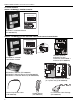
SECTION 1: INTRODUCTION SECTION 1: INTRODUCTION 1.1 What is ROBERTS GORDON® ULTRAVAC™? The ROBERTS GORDON® ULTRAVAC™ is a microprocessor based control package designed for modulating control of CORAYVAC® heaters based on outdoor temperatures. This controller is capable of giving control outputs to one vacuum pump and three heating zones. The controller also features inputs which are used for indoor and outdoor signal condition monitoring. 1.4 Check Installation Materials 1.4.
ROBERTS GORDON® ULTRAVAC™ CONTROLLER INSTALLATION MANUAL 1.
SECTION 1: INTRODUCTION URVCCM: ULTRAVAC™ Central Controller with Modem Line Voltage 120 V Wiring 1/4A + - + - + L1 POWER OUTPUT 1 OUTPUT 2 OUTPUT 3 OUTPUT 4 OUTPUT 5 OUTPUT 6 OUTPUT 7 OUTPUT 8 L2 GRD L1 L2 GRD L1 L2 GRD L1 L2 GRD L1 L2 GRD L1 L2 GRD L1 L2 GRD L1 L2 GRD L1 L2 GRD RS485 OUT RS485 OUT + - + - + - + 1 + - 2 - 3 METER INPUTS RS485 OUT RS485 OUT 1/4A 4 Modem Chip RESET OH CD RI RESS Low Voltage 24 V Wiring NC C NO NC C NO L2 L1 PWR OUT IN G +32 +5 G G G REF + - NC C
ROBERTS GORDON® ULTRAVAC™ CONTROLLER INSTALLATION MANUAL URVCCR: ULTRAVAC™ Central Controller with RS-485 Converter 1/4A - + - + - RS485 OUT RS485 OUT + - + RS485 OUT RS485 OUT 1/4A Line Voltage 120 V Wiring L1 POWER OUTPUT 1 OUTPUT 2 OUTPUT 3 OUTPUT 4 OUTPUT 5 OUTPUT 6 OUTPUT 7 OUTPUT 8 L2 GRD L1 L2 GRD L1 L2 GRD L1 L2 GRD L1 L2 GRD L1 L2 GRD L1 L2 GRD L1 L2 GRD L1 L2 GRD + - + - + - + 4 3 2 1 METER INPUTS Modem Chip RESET OH CD RI RESS Low Voltage 24 V Wiring G +32 +5 G G G REF +
SECTION 1: INTRODUCTION 1.6 Safety Your Safety is Important to Us! This symbol is used throughout the manual to notify you of possible fire, electrical or burn hazards. Please pay special attention when reading and following the warnings in these sections. Installation, service and annual inspection of controller must be done by an electrician qualified in the installation and service of control systems for heating equipment.
ROBERTS GORDON® ULTRAVAC™ CONTROLLER INSTALLATION MANUAL Zone 1 Sensor Zone 1 Zone 2 Sensor Zone 2 ROBERTS GORDON® ULTRAVAC Controller Pump Zone 3 Variable Frequency Drive Outside Sensor Zone 3 Sensor North Wall FIGURE 1: Example Site Layout NOTE: Conceptual drawing, not to scale. Venting not shown.
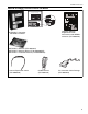
SECTION 2: SPECIFICATIONS SECTION 2: SPECIFICATIONS Shielded Cable, one twisted pair, 2.1 ROBERTS GORDON® ULTRAVAC™ Controller Wiring: 22 AWG min. 2.1.1 Enclosure NEMA 4 Enclosure for Indoor Sensor (P/N Standard Enclosure 10081510) Construction: 16 gauge painted steel, hinged Description: NEMA 4 Enclosure is sold separately door, removable knockouts as an option. The indoor sensor is provided. field mounted inside the NEMA 4 Dimensions: 14.7" w x 17.7" h x 3.5" d enclosure.
ROBERTS GORDON® ULTRAVAC™ CONTROLLER INSTALLATION MANUAL FIGURE 2: ROBERTS GORDON® ULTRAVAC™ Controller Specifications 120 Vac Outputs 120 Vac Power Input 24 V Power 1 A Fuse L1 Relay Board POWER OUTPUT 1 OUTPUT 2 OUTPUT 3 OUTPUT 4 OUTPUT 5 OUTPUT 6 OUTPUT 7 OUTPUT 8 L2 GRD L1 L2 GRD L1 L2 GRD L1 L2 GRD L1 L2 GRD L1 L2 GRD L1 L2 GRD L1 L2 GRD L1 L2 GRD 24 V Power Switch Plug-In Relays 24 V Control Board Power Supply Transformer 24 V Board 24 V Outputs Power Input 5 V TCP/IP RS 232 Sensor Module
SECTION 2: SPECIFICATIONS 2.3 Variable Frequency Drive (VFD) 2.3.1 Enclosure Standard Models Construction: 14 gauge painted steel, mounting panel included, left-hinged door, vented. Dimensions: 12" w x 14 3/8" h x 8" d Protection: UL 50 Type 1, NEMA Type 1 NEMA 4 Models Description: Drive assembly and components fully factory assembled inside NEMA 4 enclosure. Enclosure dimensions and construction vary by model.
ROBERTS GORDON® ULTRAVAC™ CONTROLLER INSTALLATION MANUAL FIGURE 3: Variable Frequency Drive Components (Factory pre-wiring shown) Rotary Disconnect Variable Frequency Drive (1 Ø input model shown) L1 L2/N PE B- Power Input B+ U V W PE 17 16 1 2 5 6 11 13A 13B 13E 25 Terminal Inputs Grounding Block PE M16/12.
SECTION 3: INSTALLATION SECTION 3: INSTALLATION WARNING Severe Injury Hazard Mount controls with materials with a minimum working load of 75 lbs (33 kg). Failure to follow these instructions can result in death, injury or property damage. Installation of the ROBERTS GORDON® ULTRAVAC™ Controller and the associated external electrical wiring must be done by an electrician qualified in the installation of control systems for heating equipment.
ROBERTS GORDON® ULTRAVAC™ CONTROLLER INSTALLATION MANUAL 3.3 Cable Requirements: 3.3.1 Line Power Supply: FIGURE 5: Indoor Sensor Cable Detail Insulation As per individual building specification for class of cable to be used. Use copper conductors only. To size the cable, use the amperages of the burners given on Page 13, Section 3.4.1, for each individual zone. 3.3.
SECTION 3: INSTALLATION 3.4 Electrical Installation Requirements DANGER Electrical Shock Hazard Disconnect electrical before servicing. This appliance must be connected to a properly grounded electrical source. Replace cover before operating. The 0-10 V signal from the ULTRAVAC™ controller enclosure wired into VFD input relays 5 and 2 (see Page 16, Figure 11 through Page 18, Figure 12) will dictate the speed of the pump.
ROBERTS GORDON® ULTRAVAC™ CONTROLLER INSTALLATION MANUAL Figure 12 for wiring details. 3.7 Indoor Sensor Placement The sensor measures the air temperature in the building. It is important that the sensor is located in an area within the heated zone at occupant level. For the most accurate results, sensors should be mounted on an inside wall, away from any air vents or other sources of heat and cold.
SECTION 4: TYPICAL EXTERNAL DIAGRAMS SECTION 4: TYPICAL EXTERNAL DIAGRAMS FIGURE 10: Central Controller Communication Equalization Wiring All ULTRAVAC™ Central Controllers are shipped with a communication equalization cable (P/N 10080450). The cable is supplied to equalize and balance the circuitry of the communications on the controller network that may be experiencing noise or transient voltage levels.
ROBERTS GORDON® ULTRAVAC™ CONTROLLER INSTALLATION MANUAL FIGURE 11: ROBERTS GORDON® ULTRAVAC™ Central Controller External Wiring To Satellite Controller RS-485 (see NOTE 2) Zone 2 Sensor (see NOTE 6) (see NOTE 6) SEN SET O/R - + SEN SET O/R - + Outdoor Sensor POWER OUTPUT 1 OUTPUT 2 OUTPUT 3 OUTPUT 4 OUTPUT 5 OUTPUT 6 OUTPUT 7 OUTPUT 8 L1 L2 GRD L1 L2 GRD L1 L2 GRD L1 L2 GRD L1 L2 GRD L1 L2 GRD L1 L2 GRD L1 L2 GRD L1 L2 GRD Zone 1 Sensor + - 8 + - + - + - + - + - + - + - + - NC C NO NC C NO NC C
SECTION 4: TYPICAL EXTERNAL DIAGRAMS ROBERTS GORDON® ULTRAVAC™ Central Controller External Wiring (continued) Zone 3 Burners Zone 2 Burners Zone 1 Burners L2 L1 L2 L1 L2 L1 L2 L1 L2 L1 L2 L1 L2 L1 L2 L1 L2 L1 Continued From Previous Page Outside Air Blower (optional) VFD Power Supply (1 Ø input VFD model shown, see NOTE 3) VFD Assembly ( 1 Ø input VFD model shown) L1 L2/N PE B- B+ To Terminal 5 17 16 1 2 5 6 11 13A 13B 13E 25 T1 M16/12.
ROBERTS GORDON® ULTRAVAC™ CONTROLLER INSTALLATION MANUAL FIGURE 12: ROBERTS GORDON® ULTRAVAC™ Satellite Controller External Wiring (see NOTE 6) (see NOTE 6) SEN SET O/R - + SEN SET O/R - + 8 +- +- +- +- +- +- +- +- NC C NO NC C NO NC C NO NC C NO L2 L1 PWR 24VAC NC C NO NC C NO NC C NO NC C NO RS232 DIRECT AUX POWER 7 OUT IN G +32 +5 G G G REF REF OUT IN RS485 COMM 1 OH CD RI 4 3 2 1 METER INPUTS RESET 10VDC 499 OHM ADDRESS OUT IN CPU OFF ON + - + - + - + - + - + - UNIVERSAL INPUTS 6
SECTION 4: TYPICAL EXTERNAL DIAGRAMS ROBERTS GORDON® ULTRAVAC™ Satellite Controller External Wiring (continued) Zone 3 Burners Zone 2 Burners Zone 1 Burners L2 L1 L2 L1 L2 L1 L2 L1 L2 L1 L2 L1 L2 L1 L2 L1 L2 L1 Continued From Previous Page Outside Air Blower (optional) VFD Power Supply (1 Ø input VFD model shown, see NOTE 3) VFD Assembly ( 1 Ø input VFD model shown) L1 L2/N PE B- B+ To Terminal 5 17 16 1 2 5 6 11 13A 13B 13E 25 M16/12.
ROBERTS GORDON® ULTRAVAC™ CONTROLLER INSTALLATION MANUAL SECTION 5: COMMUNICATIONS One ROBERTS GORDON® ULTRAVAC™ Controller per building (called the "central controller) must have equipment for remote communications to a PC. This equipment consists of either a modem chip, an RS485 converter, or a TCP/IP communications module. shielded twisted pair communication wiring. See Page 21, Figure 14.
SECTION 5: COMMUNICATIONS 5.2 RS-485 Converter for Central Controller For remote on-site viewing of system status and settings of any controller, use the RS-485 converter to connect a single PC (9 pin serial port) to the RS485 terminals on the Central Controller. This will allow communication between one PC and any of the ULTRAVAC™ controllers on the network. For RS-485 converter wiring details see Page 21, Figure 14 and see Page 25, Section 5.5 For communication cable requirements see Page 12, Section 3.
ROBERTS GORDON® ULTRAVAC™ CONTROLLER INSTALLATION MANUAL 5.3 TCP/IP Communication Module from the controller to computers on the LAN via Ethernet cable plugged into the RJ45 jack on the module. A setup procedure must be performed on the module upon installation to create its IP address on the LAN. The setup instructions can be found in the ROBERTS GORDON® Software Manual. For TCP/IP communication module wiring details, see Page 23, Figure 16.
SECTION 5: COMMUNICATIONS FIGURE 16: TCP/IP Communication Module Wiring Standard 4 Wire Phone Cord (included) Communications Circuit Equalizer Wiring (included) G G G REF REF OUT RS-232 Direct Port RS232 DIRECT AUX POWER RED BLACK BLACK RED RED +32 +5 + - OUT IN G 120 ohm resistor (included) w/ P/N 10080440 + - + - + - + - + - BLACK Shrinkwrap IN 4 3 2 1 METER INPUTS RS485 COMM RESET OH CD RI 4 Dip Switch #1 set to ON 3 CPU 2 1 + - + - + - + - ADDRESS UNIVERSAL INPUTS 6
ROBERTS GORDON® ULTRAVAC™ CONTROLLER INSTALLATION MANUAL 5.4 Direct Connect For local viewing of system status and settings of any controller, a portable PC can be connected. Using the 9 pin adapter provided, (See Page 24, Figure 17), you may wire from your computer serial port to the RS-232 direct connect port on the control board via standard 4-wire phone cable. For identification of the RS-232 direct connect port, see Page 8, Figure 2.
SECTION 5: COMMUNICATIONS 5.5 Communications Between Multiple ROBERTS GORDON® ULTRAVAC™ Controllers system status and settings can be viewed for any of the controllers on the network. If more than one ROBERTS GORDON® ULTRAVAC™ Controller is installed in a building, the controllers’ RS-485 communications must be wired in series. See Page 25, Figure 18. Connect the RS-485 terminal on controller #1 to the RS-485 terminal on controller #2 and so on in a daisy chain fashion.
ROBERTS GORDON® ULTRAVAC™ CONTROLLER INSTALLATION MANUAL 5.5.1 Repeater If the RS-485 communications wire length is above 4000', a repeater must be used to extend the signal. The repeater can also be used to create parallel branches of ROBERTS GORDON® ULTRAVAC™ controller communications bus wiring. Each repeater is sold in a 12" x 12" NEMA 1 enclosure with a 120/24 Vac transformer. There is no limit on the quantities of repeaters used in a system.
SECTION 6: VARIABLE FREQUENCY DRIVE PROGRAMMING SECTION 6: VARIABLE FREQUENCY DRIVE PROGRAMMING 6.1.2 6.1 VFD Parameter Settings For Use With ROBERTS GORDON® ULTRAVAC™ Use the arrow buttons to scroll to the password value The VFD parameters come with factory default settings. The following parameter settings must be changed for ROBERTS GORDON® ULTRAVAC™. Settings can only be altered when the pump motor is stopped.
ROBERTS GORDON® ULTRAVAC™ CONTROLLER INSTALLATION MANUAL the password must be entered in order to access the parameters again. 6.2 Altering VFD Parameters Using the procedure described in Section 6.1.1 through Section 6.1.
SECTION 7: COMMISSIONING THE CORAYVAC® SYSTEM SECTION 7: COMMISSIONING THE CORAYVAC® SYSTEM proper. If necessary, adjust the proper damper couNOTE: The ROBERTS GORDON® ULTRAVAC™ software must be installed on the PC, the communi- pling to achieve an end vent vacuum of 2.5" - 3.0" wc cation connection must be made to the controller and See Page 30, Figure 20.
ROBERTS GORDON® ULTRAVAC™ CONTROLLER INSTALLATION MANUAL FIGURE 20: End Vent Vacuum Combustion Chamber at end burner position End Vent Insert tubing about 6" (15cm) into end vent. 6 5 4 3 2 1 0 1 2 Manometer 3 4 5 6 Approximate reading after adjusting VFD frequency setting and/or damper couplings. (~ ~ 2.
Damper Zone 1 Damper Coupling NOTE: Damper setting will vary Zone 1 Damper Coupling Zone 2 Zone 2 Damper Coupling Zone 1 End Vent Zone 3 Damper Coupling Pump Damper Zone 3 Zone 2 End Vent Zone 3 End Vent SECTION 7: COMMISSIONING THE CORAYVAC® SYSTEM FIGURE 21: Possible Damper Couplings’ Locations 31
ROBERTS GORDON® ULTRAVAC™ CONTROLLER INSTALLATION MANUAL Step 7.1.3 After setting end vent vacuums between 2.5" wc and 3.0" wc, while all the burners are still operating, use the down arrow button on the VFD to reduce the frequency of the output signal to the pump. Reduce the frequency of the VFD until the manometer at each of the end vents reads 1.0" wc 1.2" wc Make note of this frequency setting below. The frequency is found on the VFD’s LCD screen. 1.0" w.c. - 1.
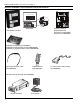
SECTION 8: REPLACEMENT PARTS SECTION 8: REPLACEMENT PARTS 8.1 ROBERTS GORDON® ULTRAVAC™ Controller Replacement Parts Caution: Use only genuine ROBERTS GORDON® replacement parts. Use of parts not specified by Roberts-Gordon voids warranty.
ROBERTS GORDON® ULTRAVAC™ CONTROLLER INSTALLATION MANUAL Part Number 10080450 10080600 07100 Description Comms Equalization Cable (not shown, located only on Central Controller) Telephone Sharing Device, 4 port Relay 120 V Unitary Lights for 150 Style Control Board Lamp Green Enclosure Mount w/o Light Lamp Red Enclosure Mount w/o Light Light Diode 24 Vac 91321614 91321615 91321616 8.2 Variable Frequency Drive Replacement Parts Caution: Use only genuine ROBERTS GORDON® replacement parts.
SECTION 8: REPLACEMENT PARTS Part Number 91321551 91321552 Description Rotary Disconnect Handle (not shown) Rotary Disconnect Rod (not shown) 8.3 Replacement Parts Instructions DANGER To fit a new Eprom, look for the notch on one end of the Eprom.There is a notch on the socket and a notch on the Eprom. The Eprom should be fit so that the notch on the socket and the Eprom are aligned. Turn on the 24 V power switch on the relay board, press the reset button on the control board and close the doors.
ROBERTS GORDON® ULTRAVAC™ CONTROLLER INSTALLATION MANUAL 8.3.6 Variable Frequency Drive 25 A or 10 A Fuse To replace a fuse, turn off input power to the variable frequency drive assembly at the breaker or disconnect switch. Turn off 120 V power to the relay board inside the ROBERTS GORDON® ULTRAVAC™ Controller. Turn off the 24 V power switch on the relay board. Inside the VFD assembly, open the fuse holder by pulling down the lever to expose the fuse. Remove the old fuse and insert a new fuse.
START Yes Yes Set the setpoint above the zone temperature. Verify scheduling times and adjust the correct setpoint (occupied or setback). Verify zone temperature sensor reading on the Board Status screen.
38 Yes Yes No Yes Is there 24 Vac across 24 V input connection #8 on the No relay board? No Is there power (120 V or 230 V) between the rotary No disconnect outputs? Replace rotary disconnect base block. Motor bearings may have failed. Repace motor. No Yes Disconnect power to the motor. Does the motor shaft turn freely? Is the pump impeller obstructed? Replace fuse. See Replacement Parts section.
No Yes Yes Do all the burners ignite smoothly? Yes After 45 seconds pre-purge period, do the burners light? Yes No No Yes Wrong end vent plate may be installed. Make sure plate and burner match. No Yes Yes Is there proper gas pressure and flow to the burners? Yes Microprocessor failure within module Ignition lockout Lockout of module after 3 tries Three flashes Normal Replace ignition module. Troubleshoot Ends Check for proper vacuum at end vent.
40 Yes Yes TROUBLESHOOT ENDS. If problems persist, contact No your ROBERTS GORDON® Independent Distributor. Yes Does the pump shut down after a 2 minute post-purge No period? Yes Do burners shut off after the call for heat is satisfied? No No Is the flame low? No Is the system leaking water? Yes No Do the burners lockout intermittently? Yes Consult wiring instructions in 200 Series Pump Manual (P/N 127200NA) or EP-300 Series Pump Manual (P/N 127202NA) for reversal instructions.
SECTION 10: THE ROBERTS GORDON® ULTRAVAC™ LIMITED WARRANTY SECTION 10: THE ROBERTS GORDON® ULTRAVAC™ LIMITED WARRANTY Roberts-Gordon is not permitted to inspect the ROBERTS-GORDON WILL PAY FOR: damaged controller and/or component parts. Within 42 months from date of shipment from RobertsGordon, replacement parts will be provided free of READ YOUR INSTALLATION, OPERATION AND charge for any part of the controller which fails due to a SERVICE MANUAL manufacturing or material defect.