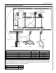
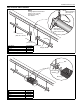
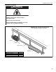
SECTION 7: HEATER INSTALLATION FIGURE 14: Critical Hanger Placement Typical Suspension Details Beam Clamp Anchor Screw Hook 3/8" 24" min.
16 Tube Reflector Burner Tube Clamp Package Burner Tube Coupling Reflector End Cap Turbulator (With Select Models) Reflector Support Tube and Reflector Hanger Burner Tube Flat Washer Nut (Torque 120 in/lb 13.56 Nm) Tube Clamp Bolt Vent Sleeve Flexible Boot U-Clips For shorter than minimum suspension lengths, tube clamp packages (purchased separately) must be used at the two farthest hangers on each side of the burner.
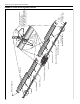
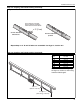
SECTION 7: HEATER INSTALLATION FIGURE 16: Linear Heater Layout Overview Linear layouts showing one side. Use same measurements for the other side.
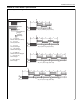
TF-SERIES INSTALLATION, OPERATION AND SERVICE MANUAL FIGURE 17: Linear Heater Layout Overview (Continued) g b c d e e e e e e e e e e e e e f 60' (18 m) Tube Length (Each Side) g b c d e e b f 70' (21 m) Tube Length (Each Side) g b c d e e b f 80' (24 m) Tube Length (Each Side) 18
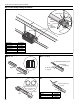
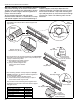
SECTION 7: HEATER INSTALLATION Step 7.1 Burner Tube Installation NOTE: Tubing requires a downward slope of 1/2" (13 mm) per 20' (6 m) away from burner. Offset mounting hole must be to the top. Weld seam must be to the bottom of the tube. 7' 6" ± 1' (229 cm ± 25 cm) S-hook 29"± 2" (73 cm ± 5 cm) Description Burner Tube S-Hook Tube/Reflector Hanger Part Number 03051XXX 91907302 03090100 Burner Tube Hanger Step 7.
TF-SERIES INSTALLATION, OPERATION AND SERVICE MANUAL Step 7.3 Tube Clamp Package Installation Tube Clamp Bolt Flat Washer Nut (Torque 120 in/lb 13.56 Nm) Description Tube Clamp Package Tube Clamp Bolt Flat Washer Nut Part Number 01318901 01396801 97113940 95211600 92113900 Step 7.4 Coupling and Tube Assembly coupling A Close with tab. Slide bar/Coupling Lock B Start onto coupling. Tab Slide Bar/Coupling Lock Wide End Coupling Open 3" (8 cm) to 4" (10 cm) Closed C Insert tubes into coupling.
SECTION 7: HEATER INSTALLATION Step 7.4.1 Coupling and Tube Assembly (Continued) Tighten slide bar as shown below Drive slide bar until tight. End of slide bar should be within tolerance listed below. ± 2" (5 cm) Correct slide bar dimensions Incorrect slide bar position • Repeat Step 7.4 A - D until all tubes are assembled. See Page 21, Section 7.4.2. Step 7.4.
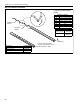
TF-SERIES INSTALLATION, OPERATION AND SERVICE MANUAL Step 7.5 Turbulator Installation Turbulator must be installed in the last standard section of tube.
SECTION 7: HEATER INSTALLATION 7.6 Reflector Installation WARNING Fire Hazard Support reflector with reflector hanger and support strap. Reflector must not touch tube. Failure to follow these instructions can result in death, injury or property damage. NOTE:All tube surfaces must be covered by a reflector, except for a U-Tube.
TF-SERIES INSTALLATION, OPERATION AND SERVICE MANUAL Step 7.6.1 Reflector, U-Clip and Reflector Support Installation The pictorial drawings of the heater construction in reflector supports and U-clips depends on the Section 7 are schematic only and provide a general individual installation. Use either pop rivets or sheet guideline of where hangers, reflector supports and metal screws instead of u-clips when installing end U-clips are to be installed.
SECTION 8: OPTIONAL HEATER ACCESSORIES SECTION 8: OPTIONAL HEATER ACCESSORIES WARNING Cut/Pinch Hazard Wear protective gear during installation, operation and service. Edges are sharp. Failure to follow these instructions can result in injury. 8.1 U-Tube Configuration The heaters are approved for optional U-Tube configurations. This installation requires 1 or 2 UTube packages depending on configuration desired. Shown below is an example of a typical 80' (24 m) UTube configuration.
TF-SERIES INSTALLATION, OPERATION AND SERVICE MANUAL FIGURE 18: U-Tube Heater Assembly Overview Reflector End Cap Reflector Turbulator Couplings Burner Tube Vent sleeves and flexible boots not shown.
SECTION 8: OPTIONAL HEATER ACCESSORIES FIGURE 19: U-Tube Heater Layout Overview U-tube layouts showing one side. Use same measurements for the other side. b c LEGEND g e Burner Reflector Tube 10' (3 m) h 20' (6 m) Tube Length* (Each Side) Tube 5' (1.
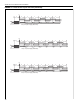
TF-SERIES INSTALLATION, OPERATION AND SERVICE MANUAL FIGURE 20: U-Tube Heater Layout Overview (Continued) b c g d e e h 60' (18 m) Tube Length (Each Side) b c g d e e f h 70' (21 m) Tube Length** (Each Side) b c g d e h 80' (24 m) Tube Length** (Each Side) 28 e e
SECTION 8: OPTIONAL HEATER ACCESSORIES 8.2 Elbow Package Configuration Step 8.2.1 Elbow Installation Tube Coupling Description Elbow Package 90° Elbow Coupling Reflector End Cap Reflector Joint Piece U-Clip Package Part Number 02718702 01335801 01312700 02750800 02750900 91107720 Minimum Distance Required Between Burner and Elbow Minimum Model Distance TF-120 10' TF-160 10' TF-200 15' TF-250 15' TF-300 15' TF-350 15' TF-380 15' 90° Elbow Step 8.2.2 Elbow Installation Tube Coupling Step 8.2.
TF-SERIES INSTALLATION, OPERATION AND SERVICE MANUAL Step 8.2.4 Reflector Joint Installation Cut away contour with tin snips. Punch/drill six 3/32" (2 mm) holes. Step 8.2.5 Reflector Joint Detail Install reflector end cap. Attach reflector joint with six #8 sheet metal screws.
SECTION 8: OPTIONAL HEATER ACCESSORIES 8.3 Reflector Side Extension Step 8.3.1 Bracket Installation Tube Reflector Tube and Reflector Hanger Reflector Support Reflector Side Extension Bracket (2 per Reflector) Use additional supports in high air movement applications. Description Reflector Side Extension Package Reflector Side Extension Retainer Clips Sheet Metal Screws Order Separately Reflector Side Extension Part Number 02712700 01368000 02751200 94118106 01329910 Step 8.3.
TF-SERIES INSTALLATION, OPERATION AND SERVICE MANUAL 8.4 Lower Clearance Shield Installation Step 8.4.1 Shield Support Strap Assembly Reflector 17" (43 cm) 12" (30 cm) Align Pilot Holes Lower Clearance Shield Locknuts Washers Description Lower Clearance Shield Package Shield Support Strap Lower Clearance Shield 8' Locknut #8 Flat Washer #8 Screw #8 x 3/8" Screws Part Number 01397501 01397500 02793000 92311400 95310800 93511406 8.5 Two-Foot Decorative Grille Installation Step 8.5.
SECTION 8: OPTIONAL HEATER ACCESSORIES Step 8.5.2 Frame Shield Installation Shield Description Deco Grille Shield Part Number 01365900 Step 8.5.3 Reflector Side Extension Installation for Decorative Grilles NOTE: If the decorative grille system is to be installed in an area with considerable air movement, it is recommended that one #8 x 3/8" sheet metal screw be installed per reflector extension to prevent it from blowing over. Cut relief notches for tube and reflector hangers. Insert screw here.
TF-SERIES INSTALLATION, OPERATION AND SERVICE MANUAL 8.6 Protective Grille Installation Step 8.6.1 Silicone Cap Installation Silicone Cap Description Grille Section Grille End Cap Silicone Cap Grille Finger Part Number 08050001 08050002 91915951-6P Step 8.6.2 Grille End Cap Installation B A Grille Grille End Cap C D Bend up 90°. Pull outward. Step 8.6.
SECTION 9: VENTING SECTION 9: VENTING WARNING Carbon Monoxide Hazard Multiburner systems are not approved for unvented use and must be vented outdoors. Vented heaters must be installed according to the installation manual. Failure to follow these instructions can result in death or injury. WARNING Cut/Pinch Hazard Wear protective gear during installation, operation and service. Edges are sharp. Failure to follow these instructions can result in injury. 9.
TF-SERIES INSTALLATION, OPERATION AND SERVICE MANUAL For 4" (10 cm) vents in either combustible or noncombustible walls, use Tjernlund VH1-4 (P/N 90502100) or equivalent, insulated vent terminal. Follow the manufacturer's instructions for proper installation. For 6" (15 cm) common vents in either combustible or noncombustible walls, use Tjernlund VH1-6 (P/N 90502101) or equivalent, insulated vent terminal. Follow the manufacturer's instructions for proper installation. 9.
SECTION 9: VENTING 9.8 Vertical Ventilation 4" (10 cm) Pipe SIDE VIEW Vent Cap 4" (10cm) Flexible Boot Boot Clamp Roof Secure all joints with (3) #8 x 3/8 Sheet Metal Screws Description Vent Cap 4" (10 cm) Single Wall Vent Pipe (Type 'B' vent pipe must be used for pipe exiting building) Burner Part Number 90502300 Flexible Boot Tube 9.
TF-SERIES INSTALLATION, OPERATION AND SERVICE MANUAL 9.10 Common Sidewall Venting TOP VIEW 6" (15 cm) Single Wall Pipe Burner Vent Terminal Tube Flexible Boot* Plan View Boot Clamp * IMPORTANT Description Vent Tee Vent Terminal 6" (15 cm) Part Number 91916100 90502101 Vent Tee Compress boot on installation to allow at least 2" (5 cm) of movement on each side for thermal expansion of tube away from the tee. 6" (15 cm) Vent Pipe 9.
SECTION 9: VENTING 9.12 Flexible Boot Installation (Common Vent) Rolled Sleeve Installation for Common Vent 18" (46 cm) 6" (15 cm) 8" (20 cm) long Flexible Boot Compressed to 6" (15 cm) long Tube 6" (15 cm) 3/4" (2 cm) Expansion Direction 3" (8 cm) Description Part Number Rolled Sleeve 09080000 Flexible Boot 4" (10 cm) 91412800 Boot Clamp 4" (10 cm) 91901300 Vent Tee - 4" Dia. x 4" Dia. x 6" Dia. 91916100 3.
TF-SERIES INSTALLATION, OPERATION AND SERVICE MANUAL 9.13 Outside Combustion Air Supply IMPORTANT: If the building has a slight negative pressure or corrosive contaminants, such as halogenated hydrocarbons, are present in the air, an outside combustion air supply to the heater is required. Seal all combustion air pipe joints. For TF-120 4" (10 cm) single wall pipe or for TF-160/200/250/300/350/380 5" (13 cm) single wall pipe, PVC pipe, aluminum flex duct, or equivalent may be used for outside air supply.
SECTION 9: VENTING 9.13.
TF-SERIES INSTALLATION, OPERATION AND SERVICE MANUAL SECTION 10: GAS PIPING WARNING Fire Hazard Tighten gas hose fittings to connect gas supply according to Figure 23. Gas hose can crack when twisted. Gas hose moves during normal operation. Use only 36" (91 cm) long connector of 3/4" nominal ID. Connector supplied with heater for U.S. models (not with Canadian models). Failure to follow these instructions can result in death, injury or property damage.
SECTION 10: GAS PIPING FIGURE 23: Gas Connection with Flexible Gas Hose CORRECT POSITIONS Shut-Off Valve (included with gas hose) must be parallel to burner gas inlet. The 3" (8 cm) displacement shown is for the cold condition. This displacement may reduce when the system is fired. 3/4" NPT Pipe CAUTION Product Damage Hazard Hold gas nipple securely with pipe wrench when attaching gas hose. Failure to follow these instructions can result in product damage.
TF-SERIES INSTALLATION, OPERATION AND SERVICE MANUAL SECTION 11: WIRING Management System. Section 11.1 below illustrates the connection for heaters controlled by a line voltage thermostat. To control multiple heaters on one low voltage thermostat, See Page 45, Section 11.2. Heaters must be grounded in accordance with applicable codes: United States: refer to National Electrical Code® NFPA 70 - latest revision; Canada: refer to Canadian Electrical Code CSA C22.1 Part I latest revision.
SECTION 11: WIRING 11.2 Low Voltage Thermostat and Relay Wiring FRONT VIEW SPST Transformer Relay 1 R 3 2 4 Black BACK VIEW COIL Low Voltage Thermostat C 6 COIL 5 W G Y Black 120 V - 60 Hz Supply Circuit Red White L1 Additional Burners L2 N Gnd. N H H Gnd. Gnd. Maximum 6 burners per relay. (See thermostat manufacturers specifications.) Burner 1 Burner 2 11.
TF-SERIES INSTALLATION, OPERATION AND SERVICE MANUAL 11.4 Ladder Diagram L1 L2 BLOWER 120V PRESSURE SWITCHES 24V IGNITION MODULE GROUND ELECTRODE GAP POWER SENSE SPARK VALVE ELECTRODE GAP LIGHT GAS VALVE 11.5 Electrical Connection to the Burner Electrical Cord or Flexible Conduit Burner Connect wires together with suitable approved wire connections. Wire Connector Green White Black Conduit Hole Green to Gnd. White to L2 Black to L1 Internal Wire Bundle L1 L2 Gnd.
SECTION 12: OPERATION AND MAINTENANCE SECTION 12: OPERATION AND MAINTENANCE WARNING DANGER Electrical Shock Hazard Disconnect electric before service or maintenance. Explosion Hazard Turn off gas supply to heater before service or maintenance. More than one disconnect switch may be required to disconnect electric from heater. Burn Hazard Allow heater to cool before service or maintenance. Cut/Pinch Hazard Wear protective gear during installation, operation and service.
TF-SERIES INSTALLATION, OPERATION AND SERVICE MANUAL equipment must perform a thorough safety inspection of the heater. For best performance, the gas, electrical, thermostat connections, tubing, venting, suspensions and overall heater condition should be thoroughly inspected. NOTE: Gas flow and burner ignition are among the first things that should be inspected. Please see Page 48, Section 12.5 for suggested items to inspect. The Vicinity of the Heater 12.
SECTION 12: OPERATION AND MAINTENANCE Outside Air Inlet Inlet must be intact. Look for obstructions, cracks on the pipe, gaps in the sealed areas or corrosion. The area must be free of dirt and dust. Clean and reinstall as required. Tubes Make sure there are no cracks. Make sure tubes are connected and suspended securely. See Page 14, Section 7. Gas Line Make sure there is no sagging, bending or distortion. Clean or replace as required. Check for gas leaks. See Page 42, Section 10.
TF-SERIES INSTALLATION, OPERATION AND SERVICE MANUAL SECTION 13: TROUBLESHOOTING DANGER Electrical Shock Hazard Disconnect electric before service or maintenance. Heater must be connected to a properly grounded electrical source. Failure to follow these instructions can result in death or electrical shock. WARNING Fire Hazard Keep all flammable objects, liquids and vapors the minimum required clearances to combustibles away from heater.
Is there spark at the igniters? Yes Turn up thermostat. Does the blower turn on? No No Check wiring between the power cord, blower motor and transformer. No Replace transformer. Yes Is the voltage at the transformer black and white leads 120 V? Carefully reset the spark gap to 1/8" (3 mm). Replace igniters and ignition wires as needed. Are the igniter gaps set at 1/8" (3 mm)? No No Yes Unplug burner and check igniters and ignition wires.
52 TROUBLESHOOT ENDS. If problems persist, contact ROBERTS GORDON ® Independent Distributor. Yes Does the burner turn off when the call for heat ends? Yes Does the burner stay on? Yes Does the burner light? Yes Yes No No No Contact Roberts-Gordon LLC at www.rg-inc.com. Check the thermostat and check the continuity of the ground wire. Replace/correct wires. No Are the wires connecting the module and electrodes OK? Yes Replace/correct wires. Replace ignition module. Replace ignition module.
SECTION 13: TROUBLESHOOTING 13.2 Manifold Gas Pressure Setting Control Side View of Heater Manometer 6 6 5 5 4 4 3 3 2 2 1 1 0 3.5" 0 1 1 2 2 3 3 4 4 5 5 6 6 Natural 10.
TF-SERIES INSTALLATION, OPERATION AND SERVICE MANUAL SECTION 14: REPLACEMENT PARTS WARNING DANGER Electrical Shock Hazard Explosion Hazard Fire Hazard Carbon Monoxide Hazard Use only genuine ROBERTS GORDON® replacement parts per this installation, operation and service manual. Failure to follow these instructions can result in death, electric shock, injury or property damage.
SECTION 14: REPLACEMENT PARTS Description Gas Valve (Natural) Gas Valve Kit (LP) (consists of NG gas valve and spring conversion kit) Gasket: (160/200/250/300/350/380) (120) Screen (160/200/250/300/350/380) (120) Blower (160/200/250/300/350/380) (120) Burner Cup Assembly Mica Window Assembly Electrode Ignition Module Electrode Gasket Indicator Light Transformer Door Switch Air Collar (160/200/250/300/350/380) (120) Transition Tube Gasket Pressure Switch: (120/380) (160/200) (250) (350) Part Number 9003370
TF-SERIES INSTALLATION, OPERATION AND SERVICE MANUAL SECTION 15: GENERAL SPECIFICATIONS 15.1 Material Specifications 15.1.1 Reflectors .024 Aluminum (Optional .024 Stainless Steel Type 304) 15.2 Heater Specifications 15.2.1 Ignition Fully automatic, three-try, direct spark, electronic ignition control, 100% safety shut-off. 15.3 Suspension Specifications Hang heater with materials with a minimum working load of 75 lbs (33 kg). See Page 15, Figure 14. 15.
SECTION 16: THE ROBERTS GORDON® VANTAGE® TF WARRANTY SECTION 16: THE ROBERTS GORDON® VANTAGE® TF WARRANTY ROBERTS-GORDON LLC WILL PAY FOR: Within 36 months from date of purchase by buyer or 42 months from date of shipment by Roberts-Gordon LLC (whichever occurs first), replacement parts will be provided free of charge for any part of the product which fails due to a manufacturing or material defect. Roberts-Gordon LLC will require the part in question to be returned to the factory.
® OWNER WARRANTY REGISTRATION CARD Mail or Fax to: Roberts Gordon LLC •1250 William Street, P.O. Box 44 • Buffalo, NY 14240-0044 • Phone: 716-852-4400 • Fax: 716-852-0854 Toll Free: 800-828-7450 • www.rg-inc.
Attach this information to a wall near the ROBERTS GORDON® heater. ® I n f r a r e d H e a t i n g Read the Installation, Operation, and Service Manual thoroughly before installation, operation, or service. Know your model number and installed configuration. Model number and installed configuration are found on the burner and in the Installation, Operation and Service Manual.