10-906 9/25/00 10:47 AM Page 1 Installation & Operating Instructions for 110-906 97302 DSL-520P COMMUNICATING ZONE THERMOSTAT
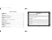
110-906 9/25/00 10:47 AM Page 2 TABLE OF CONTENTS IMPORTANT . . . . . . . . . . . . . . . . . . . . . . . . . . . . . . . . . . . . . . . . . . . . . . . . . . . . . . . . . .1 INTRODUCTION . . . . . . . . . . . . . . . . . . . . . . . . . . . . . . . . . . . . . . . . . . . . . . . . . . . . . . .2 Features . . . . . . . . . . . . . . . . . . . . . . . . . . . . . . . . . . . . . . . . . . . . . . . . . . . . . . . . . . . . . . .3 Communication . . . . . . . . . . . . . . . . . . . . . . . . . . . . .
110-906 9/25/00 10:47 AM Page 3 Local Temporary Override TABLE OF CONTENTS OCCUPIED PERIOD When in either the morning, day or evening program, the temperature setpoints may be changed at the zone thermostats by simply pressing the ✞ or ✟ buttons. The selected setpoints remain valid for the duration of the occupied period.
110-906 9/25/00 10:47 AM Page 4 IMPORTANT READ THIS BOOKLET THOROUGHLY IN ORDER TO UNDERSTAND ALL THE OPERATION FEATURES OF YOUR ENVIRONMENTAL MODULE. Changing the Temperature Setpoints Change the temperature setpoints by pressing the ✞!or ✟!buttons to lower or raise the displayed setpoint. Pressing the buttons once will display only the current setpoints that the thermostat is controlling. Press and hold to change the value.
110-906 9/25/00 10:47 AM Page 5 FAN Button This button allows selection between constant fan or auto fan mode. The constant fan mode continuously displays the ' symbol; auto fan mode means that the fan only activates when heating or cooling equipment has been activated; the ' symbol does not appear when the fan is activated during a call for cooling or heating. 1. Press and release the FAN button until the desired fan mode has been selected. 2.
110-906 9/25/00 10:47 AM Page 6 The SZP system uses 7 day programmability with 2 or 4 events per day. Programming is done at the SZP control module only. The DSL-520P thermostat provides the ability to temporarily deviate from the established program by simply pressing the ✞ or ✟ buttons to change the temperature setpoints. In addition, you may choose to display the temperature in °F or °C.
110-906 9/25/00 10:47 AM Page 7 limiting devices which provide protection against excessive current draws caused by circumstances such as wiring shorts on an output. These devices, referred to as polyfuses, are activated in general when the current draw exceeds 2.5 Amps. The value and the duration of the excess current is taken into account. The polyfuses will allow excess currents of very short duration (i.e., spikes) in order to prevent circuit interruptions by noisy lines or occasional minor surges.
110-906 9/25/00 10:47 AM Page 8 COMMUNICATION 24L: 24VAC transformer The thermostat and the SZP control module are in constant communication with each other at 1200 baud using a RS485 interface. The satellite dish symbol ✬ will appear in the lower lefthand corner of the display when the units are communicating properly. During communication the uplink symbol (✭) will flash randomly. The satellite dish symbol ✬ disappears if the DSL-520P loses communication with the SZP control module.
110-906 9/25/00 10:47 AM Page 9 4. Return the temperature setpoint to its original value. Note that selecting the OFF mode clears the ✧ symbol, ending the temporary override. and RS+V). There are no switches to set. The thermostat detects the remote sensor connection and controls temperature based on the data received. 5. Press the FAN button until the fan symbol (') appears; the green LED (fan) will light up at the SZP control module. PERIMETER HEAT 6.
110-906 9/25/00 10:47 AM Page 10 THERMOSTAT INSTALLATION: DSL-520P THERMOSTAT VERIFICATION LOCATION The thermostat operation may be verified only when the SZP control module is powered; the control module provides power to the zone thermostats. Verify operation as follows: The most important consideration in installing your DSL-520P Communicating Zone thermostat is where to locate the unit. The location can radically affect the operation of the thermostat.
0-906 9/25/00 10:47 AM Page 11 REASSEMBLING THE THERMOSTAT TO THE INSTALLED BACKPLATE INSTALLATION Before the thermostat is reassembled to the backplate, ensure the following: 1. Lift the thermostat access cover and insert a coin or large flat blade screwdriver into the slot located in the bottom center of the case and twist 1/4 turn (be extremely careful not to insert more than 1/8" [3 mm] into the casing, as this may damage the circuit board).
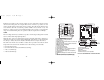
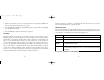
110-906 9/25/00 10:47 AM Page 12 Access Cover Assembly Housing Backplate ATTACHING BACKPLATE TO THE WALL SEPARATING THERMOSTAT AND BACKPLATE 9 DSL-520P ZONE CONNECTIONS 10
110-906 9/25/00 10:47 AM Page 12 Access Cover Assembly Housing Backplate ATTACHING BACKPLATE TO THE WALL SEPARATING THERMOSTAT AND BACKPLATE 9 DSL-520P ZONE CONNECTIONS 10
110-906 9/25/00 10:47 AM Page 11 REASSEMBLING THE THERMOSTAT TO THE INSTALLED BACKPLATE INSTALLATION Before the thermostat is reassembled to the backplate, ensure the following: 1. Lift the thermostat access cover and insert a coin or large flat blade screwdriver into the slot located in the bottom center of the case and twist 1/4 turn (be extremely careful not to insert more than 1/8" [3 mm] into the casing, as this may damage the circuit board).
110-906 9/25/00 10:47 AM Page 10 THERMOSTAT INSTALLATION: DSL-520P THERMOSTAT VERIFICATION LOCATION The thermostat operation may be verified only when the SZP control module is powered; the control module provides power to the zone thermostats. Verify operation as follows: The most important consideration in installing your DSL-520P Communicating Zone thermostat is where to locate the unit. The location can radically affect the operation of the thermostat.
110-906 9/25/00 10:47 AM Page 9 4. Return the temperature setpoint to its original value. Note that selecting the OFF mode clears the ✧ symbol, ending the temporary override. and RS+V). There are no switches to set. The thermostat detects the remote sensor connection and controls temperature based on the data received. 5. Press the FAN button until the fan symbol (') appears; the green LED (fan) will light up at the SZP control module. PERIMETER HEAT 6.
110-906 9/25/00 10:47 AM Page 8 COMMUNICATION 24L: 24VAC transformer The thermostat and the SZP control module are in constant communication with each other at 1200 baud using a RS485 interface. The satellite dish symbol ✬ will appear in the lower lefthand corner of the display when the units are communicating properly. During communication the uplink symbol (✭) will flash randomly. The satellite dish symbol ✬ disappears if the DSL-520P loses communication with the SZP control module.
110-906 9/25/00 10:47 AM Page 7 limiting devices which provide protection against excessive current draws caused by circumstances such as wiring shorts on an output. These devices, referred to as polyfuses, are activated in general when the current draw exceeds 2.5 Amps. The value and the duration of the excess current is taken into account. The polyfuses will allow excess currents of very short duration (i.e., spikes) in order to prevent circuit interruptions by noisy lines or occasional minor surges.
110-906 9/25/00 10:47 AM Page 6 The SZP system uses 7 day programmability with 2 or 4 events per day. Programming is done at the SZP control module only. The DSL-520P thermostat provides the ability to temporarily deviate from the established program by simply pressing the ✞ or ✟ buttons to change the temperature setpoints. In addition, you may choose to display the temperature in °F or °C.
110-906 9/25/00 10:47 AM Page 5 FAN Button This button allows selection between constant fan or auto fan mode. The constant fan mode continuously displays the ' symbol; auto fan mode means that the fan only activates when heating or cooling equipment has been activated; the ' symbol does not appear when the fan is activated during a call for cooling or heating. 1. Press and release the FAN button until the desired fan mode has been selected. 2.
110-906 9/25/00 10:47 AM Page 4 IMPORTANT READ THIS BOOKLET THOROUGHLY IN ORDER TO UNDERSTAND ALL THE OPERATION FEATURES OF YOUR ENVIRONMENTAL MODULE. Changing the Temperature Setpoints Change the temperature setpoints by pressing the ✞!or ✟!buttons to lower or raise the displayed setpoint. Pressing the buttons once will display only the current setpoints that the thermostat is controlling. Press and hold to change the value.
110-906 9/25/00 10:47 AM Page 3 Local Temporary Override TABLE OF CONTENTS OCCUPIED PERIOD When in either the morning, day or evening program, the temperature setpoints may be changed at the zone thermostats by simply pressing the ✞ or ✟ buttons. The selected setpoints remain valid for the duration of the occupied period.
110-906 9/25/00 10:47 AM Page 2 TABLE OF CONTENTS IMPORTANT . . . . . . . . . . . . . . . . . . . . . . . . . . . . . . . . . . . . . . . . . . . . . . . . . . . . . . . . . .1 INTRODUCTION . . . . . . . . . . . . . . . . . . . . . . . . . . . . . . . . . . . . . . . . . . . . . . . . . . . . . . .2 Features . . . . . . . . . . . . . . . . . . . . . . . . . . . . . . . . . . . . . . . . . . . . . . . . . . . . . . . . . . . . . . .3 Communication . . . . . . . . . . . . . . . . . . . . . . . . . . . . .
110-906 9/25/00 10:47 AM Page 1 Installation & Operating Instructions for 110-906 97302 DSL-520P COMMUNICATING ZONE THERMOSTAT