RS4220C RS4320C RS5220C RS6220C RS6320C 352-00061-001 Rev D INSTALLATION MANUAL RS4000C Series RS5220C RS6000C Series QUICK START STEP 1 Pull backplate straight out to remove STEP 2 Install backplate on the wall and wire STEP 3 Push front onto backplate STEP 4 Remove tape on cover STEP 5 Rotate cover up and remove battery tray STEP 6 Place batteries in tray and place in thermostat 1
Thank you for purchasing a Robertshaw® thermostat. This manual will describe how to install and test the Robertshaw two stage RS4220C, RS5220C, RS6220C and three stage* RS4320C, RS6320C thermostats. For complete operation instructions, refer to the Robertshaw User Manual. Use the model number to identify your thermostat.
IMPORTANT SAFETY INFORMATION WARNING: • Always turn off power at main fuse or circuit breaker panel before installing, removing, cleaning, or servicing thermostat. • Read all the information in this manual before installing this thermostat. • This is a 24V AC low-voltage thermostat. Do not install on voltages higher than 30V AC. • All wiring must conform to local and national building and electrical codes and ordinances.
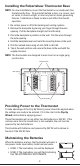
Installing the Robertshaw Thermostat Base NOTE: For new installations, mount the thermostat on an inside wall, five feet above the floor. Do not install behind a door, in a corner, near air vents, in direct sunlight, or near any heat or steam generating fixtures. Installation at these locations will affect thermostat operation. 1. Be certain power is off to the heating and cooling systems. 2. Remove the backplate by placing your finger through the wire opening.
System Switch Selection The body of the thermostat has two switches on the backside. They are accessible by removing the backplate from the body. The installer should set these to match the system. If the thermostat is controlling a heat pump system, set the first switch to Heat Pump. Set the second switch based on the type of the backup heating system. If the thermostat is controlling a non-heat pump system, set the first switch to Non-Heat Pump.
Two Stage Models RS4220C, RS5220C and RS6220C TERMINAL L Y2 EQUIPMENT TO CONNECT 24V AC Compressor Fault Output Second stage cooling connection. DESCRIPTION Connect to fault signal for input from a compressor. Energizes on a call for second stage cooling (aux.). W2 Second stage heat connection Energizes on a call for second stage heating (aux.). E Emergency Heat Connection Energizes on a call for emergency heat. If emergency heat is the same as the second stage then jumper E to W2.
Wiring Diagrams When used as Heat Pump with Cool Active Reversing Valve With Battery Transformer Hot 120 Vac 24 Vac Remove jumper if separate cooling transformer is present. Fan Relay Reversing Valve RH/R RC G O C B Compressor Fault Output (24VAC) L Compressor Contactor Y1 W1 Second Stage Cool Second Stage Heat Y2 W2 E* Emer Heat Make certain the HP switch is in the HP position.
Wiring Diagrams When used as Non-Heat Pump With Battery Backup Transformer Hot 120 Vac 24 Vac Remove jumper if separate cooling transformer is present. Fan Relay RH/R RC G O C B Compressor Contactor First Stage Heat Second Stage Cool Second Stage Heat L Y1 W1 Y2 W2 E Make certain the HP switch is in the Non-HP position. When used as Heat Pump with Cool Active Reversing Valve With Battery Backup Transformer Hot 120 Vac 24 Vac Remove jumper if separate cooling transformer is present.
Applying Power Before applying power, fill in the chart in the Pop-Up Wizard section of this manual. When 24V AC power or battery power is first applied to the thermostat, the display will show the model number followed by the Pop-Up Wizard. The thermostat will start normal operation following the Pop-Up Wizard. Power is applied to the thermostat two ways: 1. Installing the batteries. 2.
Pop-Up Wizard The Wizard routine will display factory default settings. Each setting will display for ten seconds. Use the or buttons to change the setting. Settings that are not changed will operate with the values that are displayed. To fast forward through the Wizard, press Edit Schedule. The Wizard can be exited by pressing Start/Stop Schedule. This will save the settings and place the thermostat into operation. Use this chart to write down the desired settings before applying power.
Default Settings for RS5220C, RS6220C and RS6320C The RS5220C and RS6320C series are programmable thermostats and are preprogrammed with a recommended schedule. The schedule is designed to lower energy costs year-round.
Press to step through the following: Installation Tests for Multi-Stage Models Conventional (Non-HP) Demand Terminal First Stage Heat W1 + G* Second Stage W1 + W2 + G* Heat Third Stage / N/A Emergency Heat First Stage Cool Display Heat Pump (HP) Terminal Display Y1 + G + B 2 E+G Y1 + G 2 Y1 + W2 +G + B E Y1 + G + O Second Stage Y1 + Y2 + G 2 Y1 + Y2 + G + O 2 Cool * G, will be off (not displayed) for Non-HP with Gas The display will now show the day, the setpoint, fan setting and off.
Setting Mode to Emergency Heat The multi-stage thermostats have have an emergency heat capability for heat pump systems. An E will be displayed with the heat symbol . Use emergency heat to turn off the heat pump and turn on a secondary heating source. This mode is used to bypass the heat pump when it needs servicing or when it cannot keep up with the heat demand. Setting Mode to Auto Changeover When auto changeover is active the letter A is displayed next to the and .
Thermostat Specifications Operating Voltage 18-30V AC Maximum Load Current 1 Amp Max per Output Terminal 4 Amp Total Load Output Type Latching Relays Batteries 2 AA Alkaline in Series Battery Life 2 Years Typical Ambient Operating Temperature 14 °F (-10 °C) to 122 °F (50 °C) Storage Temperature -4 °F (-20 °C) to 140 °F (60 °C) Operational Mode Chart: Demand First Stage Heat Second Stage Heat Conventional (Non-HP) Heat Pump (HP) Elec Heat Pump (HP) Gas W1 + G* Y1
Troubleshooting Problem Action Thermostat does not turn on system. Check wiring (see Wiring Diagrams section). System turns on too often. Increase temperature differential (see Pop-Up Wizard section). System fan does not operate properly. Move fan option switch to either gas or electric, to match system (see System Switch Selection section). Thermostat does not display proper room temperature. Check F/C (Fahrenheit/Celsius) setting (see Pop-Up Wizard section).
Five Year Limited Warranty Invensys Controls warrants to the original contractor installer, or to the original consumer user, that each new Robertshaw thermostat will be free from defects in materials and workmanship under normal use and service for a period of five (5) years from the date of purchase (the “Warranty Period”).
191 E. North Avenue Carol Stream Illinois 60188 USA Customer Service Telephone 1.800.304.6563 Customer Service Facsimile 1.800.426.0804 HVACCustomerService@Invensys.com Invensys™ and Robertshaw® are trademarks of Invensys plc., its subsidiaries and/or affiliated companies. All other brands mentioned may be the trademarks of their respective owners. 17 www.Uni-Line.com www.InvensysControls.
RS4220C RS4320C RS5220C RS6220C RS6320C 352-00061-001 Rev D MANUEL D’INSTALLATION Série RS4000C RS5220C Série RS6000C MISE EN SERVICE RAPIDE ÉTAPE 1 Tirez directement la plaque arrière pour la retirer ÉTAPE 2 Installez la plaque arrière sur le mur et câblez ÉTAPE 3 Enfoncez la face sur la plaque arrière ÉTAPE 4 Retirez le film du couvercle ÉTAPE 5 Faites tourner le couvercle vers le haut et retirez le bac à piles ÉTAPE 6 Mettez les piles dans le bac et puis dans le thermostat 1
Merci pour votre achat d’un thermostat Robertshaw®. Ce manuel de l’utilisateur vous servira de guide pour le réglage des thermostats RS4220C pour deux étages d’équipement, du RS5220C, RS6220C et des RS4320C et RS6320C pour trois étages* d’équipement. Consultez le manuel de l’utilisateur Robertshaw pour les instructions complètes. Utilisez le numéro du modèle pour identifier votre thermostat.
MISE EN GARDE ET CONSIGNES DE SÉCURITÉ IMPORTANTES : • Coupez toujours l’alimentation électrique au niveau du fusible ou du disjoncteur principal avant d’installer, de retirer, de nettoyer ou de dépanner le thermostat. • Lisez toute l’information de ce manuel avant d’installer ce thermostat. • Il s’agit d’un thermostat de 24 V c.a. en basse tension. Ne l’installez pas si la tension est supérieure à 30 V c.a.
Robertshaw REMARQUE : Pour les nouvelles installations, fixez le thermostat sur un mur intérieur, à une hauteur de 1,50 m. Ne l’installez pas derrière une porte, dans un coin, près des bouches d’air, à l’exposition directe du soleil ou près d’une source de chaleur ou de vapeur. L’installation dans ces emplacements aura un effet sur le fonctionnement du thermostat. 1. Vérifiez que l’alimentation du système de chauffage et de climatisation est coupée. 2.
Sélection des interrupteurs du système Le corps du thermostat est muni de deux interrupteurs au verso. Il faut retirer la plaque arrière du corps pour les voir. L’installateur doit les régler de manière à correspondre au système. Si le thermostat contrôle une pompe à chaleur, mettez le premier interrupteur en position de pompe à chaleur (Heat Pump). Réglez le second interrupteur en fonction du système de chauffage auxiliaire.
Modèles RS4220C, RS5220C et RS6220C pour deux étages d’équipement BORNE ÉQUIPEMENT À RACCORDER Sortie d’erreur du compresseur 24 V c.a. Raccord du 2ème étage d’équipement de climatisation Raccord du 2ème étage d’équipement de chauffage L Y2 W2 Raccord de chauffage d’urgence E DESCRIPTION Raccordez au signal d’erreur pour recevoir les données du compresseur. Activé par un appel de second étage d’équipement de climatisation (aux). Activé par un appel de second étage d’équipement de chauffage (aux).
Schéma de câblage Utilisation en mode de pompe à chaleur avec valve à inversion activée en climatisation avec piles Transformateur Retirez le cavalier s’ilexiste un transformateur de climatisation séparé Non utilisé avec RS 4110, RS5110 et RS6110 24 Volts c.a. Chargé 120 c.a. Relais de ventilateur G Valve à inversion O Contacteur du compresseur Y1 RH/R RC C L B Sortie d’erreur du compresseur (24 V c.a.
Schéma de câblage Utilisé en mode de non-pompe à chaleur (Non-Heat Pump) avec piles de secours Transformateur Chargé 120 c.a. 24 Volts c.a. Retirez le cavalier s’ilexiste un transformateur de climatisation séparé Relais de ventilateur RH/R G RC O C B Contacteur du compresseur 1 étage d’équipement de chauffage 2 étage d’équipement de climatisation 2 étage d’équipement de chauffage L Y1 er W1 ème ème Y2 W2 E Veillez à ce que l'interrupteur de pompe à chaleur soit sur « HP ».
Mise en circuit Avant de fournir l’alimentation électrique, complétez le tableau dans la section du guide intelligent de ce manuel. Lorsque le thermostat est alimenté pour la première fois en 24 V c. a. ou avec des piles, l’écran affiche le numéro du modèle et ensuite le guide intelligent. Le thermostat commence le fonctionnement normal après l’activation du guide intelligent. Il existe deux façons d’alimenter le thermostat : 1. Installation des piles: 2.
Guide intelligent Le guide intelligent affichera les réglages d’usine. Chaque réglage sera affiché pendant dix secondes. Utilisez les touches et pour changer le réglage. Les réglages non modifiés fonctionneront avec les valeurs affichées. Pour défiler rapidement à travers la séquence du guide intelligent, appuyez sur « Edit Schedule ». Pour sortir du guide intelligent, appuyez sur « Start/Stop Schedule ». Ceci enregistrera les réglages et mettra le thermostat en mode de fonctionnement.
Réglages pour RS5220C, RS6220C et RS6320C Les modèles des séries RS5000 et RS6000 sont des thermostats programmables et ils sont programmés avec un calendrier recommandé. Ce programme est conçu pour abaisser les coûts énergétiques pendant toute l’année.
Appuyez sur pour faire dérouler les éléments suivants : Tests de l’installation pour les modèles avec plusieurs étages d’équipement Conventionnel (non thermopompe « Non-HP ») Demande Borne Pompe à chaleur (« HP ») Affiché 1 étage d’équipement W1 + G* de chauffage 2ème étage 2 d’équipement W1 + W2 + G* de chauffage 3ème étage d’équipement Sans objet de chauffage 1er étage d’équipement Y1 + G de climatisation 2ème étage 2 d’équipement Y1 + Y2 + G de climatisation Borne Affiché er Y1 + G + B 2 Y1 +
Réglage en mode de chauffage d’urgence Les thermostats pour matériel multi-étagé ont une capacité de chauffage d’urgence pour les systèmes avec thermopompes. Un E sera affiché avec le symbole du chauffage . Utilisez le chauffage d’urgence pour éteindre la pompe à chaleur et mettre en route une source de chaleur auxiliaire. Ce mode est employé pour contourner la pompe à chaleur quand elle a besoin d’entretien ou quand elle ne peut pas répondre à la demande de chauffage.
Caractéristiques du thermostat Tension 18-30V c. a.
Vérification-dépannage Problème Action Le thermostat ne met pas le système en route. Vérifiez le câblage (Voir la section sur les schémas de câblage). Le système se met en route trop souvent. Augmenter le différentiel de la température (Voir la section sur le guide intelligent) Réglez le commutateur du ventilateur sur l’option gaz Le ventilateur du système ne fonc- ou électricité de manière à tionne pas correctement.
Garantie limitée de dix-huit mois Invensys Controls garantit à l’installateur sous-traitant d’origine, ou à l’utilisateur consommateur d’origine, que chaque thermostat Robertshaw neuf ne comportera aucun défaut de pièces et de main d’œuvre dans des conditions d’utilisation et d’entretien normales pendant une période de dix-huit (18) mois à compter de la date de fabrication (la « Période de garantie »).
Certains Etats n’autorisent pas l’exclusion ou la limitation des dommages induits ou secondaires, ou n’autorisent pas de limitations de la durée d’une garantie implicite, il est donc possible que les limitations ou exclusions ci-dessus ne s’appliquent pas à vous. La présente Garantie vous confère des droits juridiques spécifiques, et il est possible que vous ayez d’autres droits qui varient d’un Etat à un autre.