
Owner's Manual


3
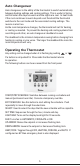
Installing or Changing the Batteries
To remove the battery compartment gently
squeeze the ribbed edges on both sides.
The battery compartment will pull down
from the thermostat body and will detach.
Install two AA batteries following the polarity
as shown inside the compartment. Place
compartment back into the thermostat.
When the batteries are low the thermostat will
enter a low battery mode.
Low battery mode has two levels.
• LEVEL 1: The low battery icon will be displayed. The
thermostat will continue to operate. Replace the
batteries as soon as possible
• LEVEL 2: The low battery icon will flash. If 24V AC
is present the thermostat will continue to operate if
the batteries are discharged or removed. If 24V AC
is not present the thermostat runs on batteries only
and THE SYSTEM WILL NOT OPERATE. Replace
batteries immediately.
Replace batteries if leaving thermostat unattended for more than
30 days.
The clock will continue to run for 10 minutes when the batteries
are removed.
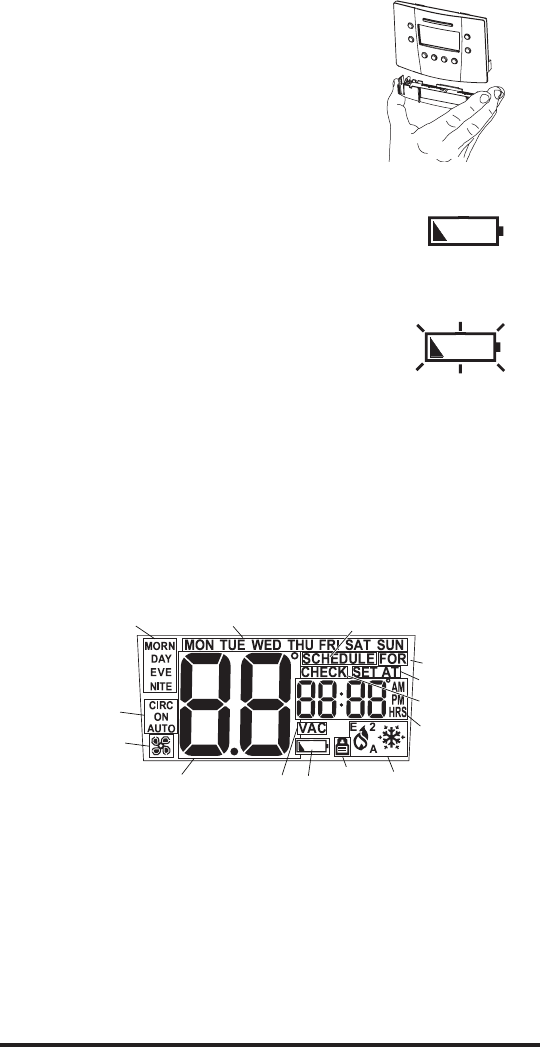
Display Description
The thermostat display will show information that is being used during
operation or programming. This illustration shows all of the display’s
possibilities with an explanation.
2
1. Event Names (used for editing schedule).
2. Day is displayed on Idle screen. Also used to display day ranges
when editing the schedule (e.g., SAT SUN for weekend).
3. Used with clock to display hold duration (e.g., FOR 2h).
4. On when running a schedule.
5. Used with setpoint.
6. Used along with clock for service reminders (e.g., CHECK HP).
7. Used for time, current setpoint, and some configuration data (e.g.,
filter hours).
8. HVAC mode and status. Icons blink when active. A is for Auto, 2 is
for second stage, E is for emergency.
9. Indicates when security is active.
10.Low battery indicator.
11.Not used.
12.Used for ambient temperature and configuration data (e.g., first
stage differential, F or C, etc.).
13.Fan status (rotates when active).
14.Fan mode selected by pressing FAN button.
5
3
4
1
6
7
8
9
10
12
11
13
14