
Specifications


http://www.ppwatt.com
Tweed 5E3 PCB Valve Junior Conversion
Build Manual v3.0 13 Feb 2011
15 of 40
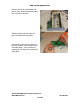
I prefer laying the PCB on the outside of the chassis & marking the new drill
holes on the outside as I only have a hand drill to use.
Notice the PT has been unbolted from the chassis so that it can be moved over
enough that the PCB can be lined up correctly with the existing stand-offs. You
could just remove it entirely at this stage.
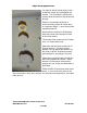
Mark the existing
stand-offs so that
you can use them
to line up the PCB
& then lightly tape
it to the chassis.
Use a felt tip
marker to then
mark where the
new drill holes are
to go.
This way you will be able to drill the chassis holes from the outside of the chassis
with a hand drill and not drill holes in the top of your workbench!
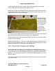
7KHEOXHDUURZSRLQWVWRWKHH[LVWLQJSRZHUWXEHKROHWKDW\RX¶OOQHHGWRHQODUJH
to cater for the Octal base.
Note the circled grommet. This is a new hole that you should drill to take the OT
µLQSXW¶ZLUHVWKDWFRQQHFWWRWKH3&%,ILQGLWDELWRIDVTXDVKWU\LQJWRJHWDOORI
the wires from the new OT through the one existing hole.
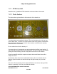
6.1.2 Layout the Faceplate for drilling
We have developed a number of professional grade faceplate options for the
Tweed 5E3 PCB. The information is on the web site. We highly recommend you
buy or fabricate one of these faceplates and use it to layout the front panel drill
ORFDWLRQV,W¶VPXFKPRUHDFFXUDWHWRXVHWKHDFWXDOIDFHSODWHWKDQLWLVWRXVHD
drill plan printout.
If you have a faceplate, align the faceplate with the front of the chassis and trace
each drill location.