Learn Build Play Assembly Manual Tweed 5E3+ Instructions for Assembling with the: - Printed Circuit Board (PCB) with additional modification suggestions and recommended amp settings version 20 15 May 2014
This manual was developed and published by: TubeDepot.com Memphis, TN Written by: Robert Hull Edited by: Mary Klaebel Design and artwork by: Robert Hull Mary Klaebel Christian Magee Acknowledgements: Special thanks to: Joe Austin Matt Kirby Henry Lum Brian Overstreet Doug Sims Ben Siler Special Thanks to Steve Zeller, Todd Fox, Skip Black, Jake Swiatek and Henk Haitjema for their invaluable proofreading skills. Copyright © 2009 TubeDepot.com 1686 Barcrest Dr.
Table of Contents page Preface and Tweed 5E3 overview ................................................................................................. iv Chapter 1 Safety …......................................................................................................................... 1 Chapter 2 Tools and Supplies …..................................................................................................... 2 Chapter 3 Parts Inventory ...........................…...........................
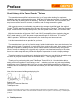
Preface Short History of the Tweed Fender TM Deluxe The tweed deluxe amplifier has become the “go to” amp when looking for maximum portability and raw, uncompromising tone. With two 6V6 tubes and a single 12” speaker, the tone of this amp is nothing short of amazing. Used by a “who's who” list of musicians, this amp's tone can be found on records, in studios, and on stage around the globe.
1 Safety !!! Read these safety precautions before continuing !!! ALL tube amplifiers contain LETHAL VOLTAGES, often several hundred volts which WILL leave burnt entrance and exit wounds in skin. These voltages have the potential to cause permanent physical damage and death. These voltages are present when the amp is turned on and also for some time after the amp has been turned off. You can still get shocked with a tube amp turned off and disconnected from AC power.
2 Tools and Supplies As with any construction project, there are certain tools and supplies that are recommended to complete the project. These are tools and supplies not provided with the kit and are instead provided by the builder. TubeDepot.
3 Parts Inventory It is important to review all the parts that came with your kit. The list below is what you should have received to complete your kit. If you find anything missing, contact us: Qty Description TubeDepot.com 1686 Barcrest Dr. Memphis, TN 38134 (877) 289-7994 info@tubedepot.
2 screw, zinc plated 8-32 x 1/4", phillips pan head 1 screw, zinc plated #6 philips pan head 2 solder lug, locking, #8 screw 2 solder lug, locking, #6 screw 1 header, 3 pin / two position 1 shorting jumper 3 ft. alum.
4 Cabinet Preparation This chapter deals with preparing the cabinet for installation of the completed chassis. But first, we need to take inventory of the parts that came installed on the cabinet. 1. Handle w/ mounting hardware – There should be a single flat brown leather handle with two metal securing ends all fastened to the cabinet with four screws. 2. Feet, chrome metal glide – There should be four metal feet attached with screws to the underside of the cabinet. 3.
holes and install the chassis mounting bolts. Step 10 – Test fit the chassis onto the bolts to make sure the holes are properly aligned. Step 11 – Remove chassis and reinstall handle, leaving chassis mounting bolts installed. Proceed to 4.2 4.2 Installing the Speaker Step 1 – Remove the four nuts from the speaker mounting bolts inside the cabinet. Step 2 – Remove the speaker from its shipping box. With speaker in hand, carefully align the speaker mounting holes to the baffle bolts.
NOTE The ¼” phone plug was invented for use in telephone switchboards in 1878. Although it is no longer used for telephone switching, this great plug has become the standard connection type between musical instruments and outboard equipment. photo 4.3c Step 6 – Solder these wires to the solder terminals of the speaker; the white wire to the “+” terminal and the black wire to the “-” terminal (photo 4.3d). Proceed to 4.4 4.
5 Circuit Assembly Here is where good soldering skills and attention to detail will pay off. By following these directions, you should have no trouble in completing the circuit assembly quickly and without errors. I encourage you to first read all the steps to familiarize yourself with not only the installation flow, but also the components to be used. Appendix A has explanations on how to read the value codes found on both the resistors and capacitors.
Step 5 – Install a 2.7K (2,700) ohms / ½ watt resistor (red, violet, red, gold) in position R23. Step 6 – Install a 47 ohms / ½ watt resistor (yellow, violet, black, gold) in position R24. Step 7 – Install 1.5K (1,500) ohms / ½ watt resistors (brown, green, red, gold) in positions R12 & R14. Step 8 – Install 220K (220,000) ohms / ½ watt resistors (red, red, yellow, gold) in positions R17 and R18. Step 9 – Install a 1M (1,000,000) ohms / ½ watt resistor (brown, black, green, gold) in position R13.
5.2 Installing Feedback Header / Jumper J1 Step 1 – Locate position J1 on the board. It is identified by the three small pads next to the printed word “feedback”, above the large letter “G”. Step 2 – Install the three pin header in these three holes (photo 5.2a / b). Step 3 – Install the jumper onto the two pins nearest R23 (the “out” position). photo 5.2a Proceed to 5.3 NOTE photo 5.2b With the FEEDBACK jumper in the “OUT” position, the amp will have stronger midrange response and be quick to distort.
5.4.2 Red Wires (Circuit B+ and Preamp Tube Inputs) Step 1 - Strip back the insulation from the end of the red wire 1/8” and tin the end of the exposed strands. Insert the tinned end of this wire into the pad labeled “a” and solder. Measure and cut this wire to a length of 3” from pad “a”. Step 2 – Repeat above for pads “b”, “d”, and “e”. Step 3 – Repeat above for pads “x” and “y” except extend the wires to 3.5”. Step 4 – Repeat above for pad “j” except extend the wire to 3.5”. Proceed to 5.4.3 5.4.
6 Chassis Preparation 6.1 Drilling Mounting Holes for the Printed Circuit Board (PCB) There are two acceptable methods for determining where to drill the holes for mounting the circuit board, the template method (6.1.1) and the positional method (6.1.2). Choose the method that works best for you. 6.1.1 Template Method photo 6.1a photo 6.1b Step 1 – Locate the template “drilling template chassis/5E3” in Appendix D2. Verify that the template drill markings correctly align with the PC board mounting holes.
(photo 6.1c). Step 4 – Place the circuit board on the chassis. Align one of the short edges of the circuit board against the mark on the masking tape and center the two long edges equally between the two chassis sides (photo 6.1d). Step 5 – With a permanent marker, place a mark on the chassis through each of the four holes at each corner of the circuit board. Step 6 – Remove the circuit board.
6.4 Proceed to 6.4 Mounting the Output Transformer NOTE The various output transformers available with this kit have differing wire colors.. Refer to appendix F for applicable installation directions and options. Step 1 – Twist the primary wires together (red, brown and blue). Step 2 – Twist the secondary wires together (either yellow and black; or green and black; or yellow, black and brown wires). Step 3 – Feed the two wire sets into the grommets (photo 6.4a).
6.7 Mounting the Fuse Holder Step 1 – Remove the nut from the fuse holder and insert the fuse holder into the corresponding chassis opening. The rubber gasket should be situated on the outside of the chassis. Step 2 – Reinstall the threaded nut on the fuse holder and tighten it against the chassis. Step 3 – Keep the nut from loosening by painting the exposed threads with fingernail polish (photo 6.7a). Proceed to 6.8 6.8 Mounting the Power Switch Step 1 – Remove all mounting nuts from the switch.
Step 3 – Place the flat washer on the outside of the chassis and then install and tighten the hex nuts with a 1/2” socket. NOTE Various output transformers are available with this kit. The wire colors differ between these transformers. Refer to appendix F and / or the TubeDepot online resources for appropriate installation instructions. Photo 6.
Step 4 – Insert a #6 x 1/4” screw into the mounting hole of the V2 socket nearest the chassis edge. Secure this screw with a #6 KEPS nuts. Step 5 – Bend a #6 solder tab at a slight angle. Step 6 – Insert a #6 x 1/4” screw into the remaining mounting hole of the V1 socket. Step 7 – Install the #6 solder tab and #6 nut (not a KEPS nut) (photo 6.12e). Tighten firmly. Proceed to 6.13 photo 6.12f Photo 6.12g 6.12.
Step 4 – Remove the masking tape and finish tightening the nuts down to the board. Step 5 – Locate the 3” wire attached to the V1 tube socket solder tab. Solder the opposite end of this wire to the PC board mounted solder tab from step 1 above. This grounds the frame of V1 tube socket (drawing 6.13c). Proceed to 6.14 6.14 Mounting and Wiring the Input Jacks photo 6.
6.15 Wiring the Ground Buss Step 1 – With a small knife, scratch a spot through the yellow plated coloration on the back of each potentiometer approximately 1/4” diameter in the center of each of the three mounted pots, exposing the bare metal underneath (photo 6.15a). NOTE NOTE Solder will not adhere to the protective plating used on the rear of the potentiometers. By removing a small area of the plating on exposing the underlying bare metal, solder will adhere. photo 6.
the middle terminal of the normal channel volume control (photo 6.17a and drawing 6.17b). Step 4 – Strip and tin the end of the yellow wire coming from pad “f” and lightly tack this wire in place at the middle terminal of the bright channel volume control (photo 6.17a). Do not fill the terminal with solder just yet. NOTE photo 6.17a “Tacking” a wire means to apply just enough solder to hold the wire in place.
transformer. Connect these two wires to pins 8 and 2 (top opening of pins) of the rectifier tube socket. Solder pin 2 but don't solder pin 8 just yet (photo 6.18a). There are more wires to add later. Proceed to 6.19 photo 6.19a 6.19 Wiring the Standby Switch Step 1 – Cut a piece of red wire 6” long and strip and tin both ends. Connect one end of this wire to pin 8 of the rectifier tube socket. Solder the wires together on this pin.
coming from pad “p”. Step 14 – Twist these two wires tightly together and route the wires along the bottom edge of the chassis. Step 15 – Solder the wire from pad “p” (the one with the mark) to pin 6 of the octal socket nearest the rectifier tube socket. Step 16 – Solder the wire from pad “q” to pin 6 of the octal socket nearest the preamp tube socket. Step 17 – Neatly organize all wires against the chassis. Proceed to 6.21 photo 6.21a 6.
Step 5 - Trim, strip and tin the red wire from pad “y”. Solder this wire to pin 2 of the preamp tube socket V1 (photo 6.23a ). Step 6 - Trim, strip and tin the yellow wire from pad “z”. Solder this wire to pin 3 of the preamp tube socket V1. Step 7 – Neatly organize all wires tightly against the chassis (photo 6.23a). Proceed to 6.24 photo 6.24a 6.24 Installing and Wiring the Filaments Step 1 – Fold the 18 AWG length of green wire in half and twist the two ends together.
Step 9 – Neatly route this twisted wire pair to the 9 pin preamp tube socket on the opposite side of the speaker jacks (socket V2). Trim wire to length, strip and tin these ends and tack them in place to pins 9 and pins 4 and 5 of this tube socket (photo 6.24d). Step 10 – Untwist 1” from the cut ends of the twisted pair wires. Strip and tin these ends and solder (along with other wires) to pins 9 and pins 4 and 5 of the above preamp tube socket (V2).
corresponding hole in the chassis. Step 5 – While still grasping the strain relief with the pliers, guide the strain relief into the chassis hole. Firmly press the compressed strain relief into the chassis hole (photo 6.25b). NOTE There is a specific tool that makes installing strain reliefs simple. If you find yourself installing strain reliefs on a regular basis, this tool is worth owning. See TubeDepot.
Dual Primary Power Transformer Installation Instructions. Choose the installation appropriate for your mains supply voltage (120V or 240V). 6.30a CAUTION Wiring the Power Transformer for 120V Mains It is important to choose the correct primary wires based on the mains voltage appropriate to your location in the world. Incorrect wiring can lead to power transformer damage and/or fire hazards. The following instructions are for wiring the dual primary transformer for 120V mains.
drawing 6.30b drawing 6.30a TubeDepot.
7 Final Assembly 7.1 Installing the Knobs Step 1 – Rotate the shafts of the controls on the front of amp fully counter clockwise Step 2 – with a small screwdriver, loosen the set screw of the first knob Step 3 – Place this knob on to the first control shaft. Step 4 – Align the pointer of the knob to the “1” position printed on the chassis. Step 5 – firmly tighten the set screw of the knob to the shaft. Step 6 – Repeat for remaining knobs and shafts. 7.
8 Testing are almost finished. And although the first temptation is to plug in the amp and 8.1 You turn it on, I recommended taking the time to review all of your work. Any errors are more likely to stand out during this time. It is common to find two or more errors. After verifying the connections are correct, read all of the following steps before completing any of them. Once you have finished reading these steps, it is time to begin.
(B+). The voltage here should be something close to +460 +/10 volts (photo 8.1b). WARNING NOTE Whenever testing voltages, it is recommended to keep your free hand off of the chassis. In this way, there isn't a path for significant current to flow through the body to ground in case the measuring hand accidentally comes in contact with high voltages. These voltages are being measured without power and preamp tubes installed. These values will decrease with the added load of the tubes.
carefully connect the meter's black lead to chassis ground and the red lead to the positive side of C10. The voltage here should read close to +22 +/- 3 volts (photo 8.1e). NOTE The presence of voltage at step 22 indicates that V3 and V4 are correctly sourcing current. Step 24 – If all the above measurements are within specifications, and the speaker is connected, and with no signal source connected to either input, turn up the volume control and listen for a low level hiss from the speaker.
9 M Schematics Visit our website for higher resolution versions of these drawings, schematics and diagrams. 32 TubeDepot.
Parts and Wiring Layout Visit our website for higher resolution versions of these drawings, schematics and diagrams. TubeDepot.
10 Cool Modifications Once you have the amp working and sounding good, here are a few ideas to “shape” the tone to suite your tastes. 1. Reduce low frequency muddiness when running the amp at high gain settings by changing both C1 and C2 from .1ufd to .047ufd or .022ufd or .01ufd or even .0047ufd! Make sure to change both equally. 2. Change both C8 and C9 like above.
A Appendix A Resistor and Capacitor Codes This project uses different types of resistors and capacitors. The diagrams below will assist you in locating and identifying values, tolerances and ratings for the various circuit requirements for your project. Resistor Power Ratings Not only are resistors graded by their values but also by their power ratings. Power ratings are determined by how much heat (power) can be safely dissipated by the resistor. Higher ratings are usually indicated by larger sizes.
Resistor Value Color Codes Resistor Types Carbon Film Metal Oxide Carbon Composition 1st Digit Color Digit Black Brown Red Orange Yellow Green Blue Violet Gray White 0 1 2 3 4 5 6 7 8 9 Color Black Brown Red Orange Yellow Green Blue Violet Gray White Digit Color Multiplier 0 1 2 3 4 5 6 7 8 9 Black Brown Red Orange Yellow Green Blue 1 10 100 1,000 10,000 100,000 1,000,000 Color Digit 3rd Digit Black Brown Red Orange Yellow Green Blue Violet Gray White 0 1 2 3 4 5 6 7 8 9 Silver Gold Metal
How to Read Capacitor Value Codes This project uses several different kinds of capacitors. Some of these capacitors have their values and voltage ratings printed on them, others use numerical codes. The diagrams below will assist you in locating and identifying capacitor values, tolerances, and voltage ratings for the various circuit requirements for your project.
B Appendix B Soldering Hints Anyone working in electronics should learn how to solder well. Thankfully it isn't hard, it just takes practice and having the proper tools. Once you are able to solder well, your projects will be more professional and more reliable. Refer to our video “How To Solder” for detailed explanations. http://www.youtube.
4. When applying the soldering iron to a connection to be made, it is important to lay the tip in such a position that the maximum surface area of the tip is presented to the connection. In this way, the maximum heat is transferred to the connection in the minimal amount of time. 5. Apply solder to the work and not the iron. In this way, a properly heated connection will readily accept the solder, further reducing the chances for unreliability. 6. Use only clean, good quality, rosin core solder.
C Appendix C Amplifier Care, Feeding, and Applications Now that your amp is finished, here are a few hints to keep it up and running and you safe and happy: – Only plug this amp into properly grounded (three prong) AC receptacles. – Do not cut off the third prong of the power cord plug thus defeating this safety feature.
Applications The laboratory environment is nice, but field experiences better determine success. Therefore the true test of a good amp is how well it performs “in the field”. The following are some of my favorite field proven gigging and recording hints. – Run this amp wide open! Let it breath, let it sing. It wants to be heard. – Insert the guitar or harp mic into the BRIGHT #1 jack. With a short (6”) 1/4” to 1/4” patch cable; insert one plug of this cable into the BRIGHT #2 jack.
D Appendix D Templates Appendix D1 is the cabinet drilling template ….............................................................. Appendix D2 is the chassis drilling template – PCB and Turret Boards ….................... 42 TubeDepot.
APPENDIX D-1 Make sure the printer is set to print 100% original size to insure a correctly sized template. Adjust size as needed to get correct ratios. The templates included in the manual may be incorrectly sized therefore, it is important to measure prior to cutting. Visit our website for higher resolution versions of these drawings, schematics and diagrams. Fold along this line Fold along this line TubeDepot.
APPENDIX D-2 The templates included in the manual may be incorrectly sized therefore, it is important to measure prior to cutting. Visit our website for higher resolution versions of these drawings, schematics and diagrams. 44 TubeDepot.
E Appendix E Test Equipment Load Box The following load box can be used between an amplifier and a speaker to reduce the volume of the amp and still get distortion. The values are set for a speaker impedance of 8 ohms and an amplifier wattage of no more than 20W. I've listed several different resistor value sets to choose from based on how much signal power you want making its way to the speaker. I recommend building everything inside a small metal box.
F Appendix F Output Transformer Wiring Options There are different Tweed 5E3+ style output transformers we source for this kit, all of which have slightly different secondary options. From the drawings below, select the drawing that corresponds to the output transformer that came with your kit. Wire your amp accordingly.