
Specifications


Step 5 – Install a 2.7K (2,700) ohms / ½ watt resistor (red,
violet, red, gold) in position R23.
Step 6 – Install a 47 ohms / ½ watt resistor (yellow, violet,
black, gold) in position R24.
Step 7 – Install 1.5K (1,500) ohms / ½ watt resistors (brown, green, red, gold) in positions
R12 & R14.
Step 8 – Install 220K (220,000) ohms / ½ watt resistors (red, red, yellow, gold) in positions
R17 and R18.
Step 9 – Install a 1M (1,000,000) ohms / ½ watt resistor (brown, black, green, gold) in
position R13.
Step 10 – Install a 56K (56,000) ohms / ½ watt resistor (green, blue,
orange, gold) in positions R11 and R15.
Step 11 – Install a 22K (22,000) ohms / 1 watt resistor (red, red,
orange, gold) in position R22.
Step 12 – Install a 4.7K (4,700) ohms / 3 watt resistor (yellow, violet,
red, gold) in position R21.
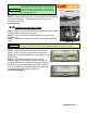
Step 13 – Install a 250 ohms / 5 watt (or upgrade to the 8W Brown
Devil) resistor in position R20 (photo 5.1a).
Capacitors
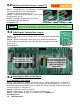
Step 14 – Install a .022ufd coupling capacitor (223) in position C7. It is important to install the
capacitor leads in the two holes as shown in photo 5.3b. This capacitor does not have a
polarity and can be installed in either direction.
Step 15 – Install a .1 ufd coupling capacitor (104) in positions C1, C2, C8 and C9. These
capacitors do not have a polarity and can be installed in either direction.
Step 16 – Install a 22ufd / 50V electrolytic capacitor in positions C3, C6, and C10. These
components have a polarity, therefore they must be installed according to case and board
markings. The arrow points to the negative lead.
Step 17 – Install a 22ufd / 500V electrolytic filter capacitor in positions C12, C13, and C14.
These components have a polarity, therefore they must be installed according to case and
board markings (photo 5.3b).Proceed to 5.2
TubeDepot.com 9
CAUTION
Electrolytic capacitors DO have a polarity and must be installed according to the markings
on the component and the PC board. The arrow on the case points to the negative lead
The on-board positions for all coupling and electrolytic capacitors have additional pads for
accommodating different lead spacings of different sized components. It is recommended to
utilize the pad spacings that closely match the leads of the component you are installing.
NOTE
When installing electrolytic caps, it is good practice to install the component with the value,
voltage rating, and polarity markings facing up. This makes reading the component easier.
NOTE
NOTE
Position C7 is critical to overall tone shaping of the amp. If after you have assembled the
amp the tone is too muddy sounding, try changing C7 value to .01 or .0047 to reduce the low
end response of the amp. I usually install a .01 ufd cap here by default.
NOTE
When installing large electrolytic caps, it is good practice to secure the component to the
board with a small bead of silicon adhesive. This will keep the component firm against the
board, removing the chance for the component to vibrate when the amp is played.
NOTE
Many small tube amps from the late 50's into the mid 60's used Ohmite “brown devil”
resistors as the cathode resistor of the power tube(s). Although more expensive, this is the
preferred resistor to use because of its durability and small size. And it looks great too!
photo 5.1a