
Specifications


Proceed to 6.4
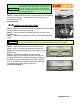
Mounting the Output Transformer
Step 1 – Twist the primary wires together (red, brown and blue).
Step 2 – Twist the secondary wires together (either yellow and
black; or green and black; or yellow, black and brown wires).
Step 3 – Feed the two wire sets into the grommets (photo 6.4a).
The red, blue and brown primary wires go into the grommet
nearest the power transformer (see appendix F for various
output transformer wiring options).
Step 4 – Pull the two wire bundles tightly through the grommets
Step 5 – Secure the output transformer to the chassis with two #8 KEPS nuts and the two #8
x 1/4” screws. The two KEPS nuts should be mounted on the inside of the chassis.
Proceed to 6.5
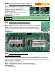
Mounting the three 1M potentiometers
Step 1 – Locate the three 1M potentiometers and the three
3/8” lock washers.
Step 2 – Remove the nut and flat washer from each pot.
Remove the keying tab (by cutting off or bending out of the
way) flush from each pot (photo 6.5a)
Step 3 – Install a lock washer on each pot (photo 6.5b).
Step 3 – Insert each pot with appropriate lock washer
into corresponding hole in chassis (lock washer should be on the inside of
chassis).
Step 4 – Rotate each pot where solder terminals are facing toward the
outside of the chassis (photo 6.5c)
Step 5 – Tighten all nuts with a 1/2” socket.
Proceed to 6.6
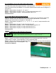
Mounting the Indicator Lamp
Step 1 – Remove the nut from the bezel holder.
Step 2 – With the nut removed, remove the lamp frame.
Step 3 – Place the bezel holder through the corresponding opening in the
chassis.
Step 4 – Install the lamp holder on the threaded end of the bezel holder.
Step 5 – Thread the nut onto the threaded end of the bezel holder.
Step 6 – Position the indicator lamp with the lamp frame toward the chassis
(photo 6.6a).
Step 7 – Tighten the nut to firmly secure the assembly to the chassis.
Step 8 – Apply a drop of fingernail polish to the threads and nut to lock in place (photo 6.7a).
Proceed to 6.7
6.4
14 TubeDepot.com
6.5
6.6
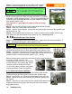
By placing the point of a center punch on one of the corners of the lamp assembly nut and
tapping the center punch, the nut can be firmly tightened
NOTE
photo 6.4a
photo 6.5a
photo 6.6a
photo 6.5b
photo 6.5c
remove this tab
NOTE
The various output transformers available with this kit
have differing wire colors.. Refer to appendix F for
applicable installation directions and options.