Italiano Il libretto istruzioni è parte integrante del prodotto. - The instruction booklet is an integral part of the product.
Italiano Gentile Cliente, La ringraziamo per aver preferito uno dei nostri prodotti, frutto di lunga esperienza e di una continua ricerca per un prodotto superiore in termini di sicurezza, affidabilità e prestazioni. In questo manuale troverà tutte le informazioni ed i consigli utili per poter utilizzare il suo prodotto nel massimo della sicurezza ed efficienza.
Capitolo Titolo Pagina Codice 1.
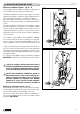
Italiano 1.0 NORME GENERALI DT2010168-00 Prima di procedere con l’installazione scegliere la posizione più adatta all’installazione del vostro caminetto in base alle prescrizioni indicate al paragrafo “DISTANZE MINIME DI SICUREZZA” ed a tutte le voci sotto elencate. Fig.
DT2010169-00 1.1 CAMINO O CANNA FUMARIA SINGOLA - Fig. 2 ÷ 6 Fig. 2 Italiano Ogni apparecchio a tiraggio naturale deve avere un condotto verticale, denominato canna fumaria per scaricare all’esterno i fumi prodotti della combustione.
DT2010025-02 Italiano 1.3 COMIGNOLO - Fig. 7 ÷ 11 Il comignolo è un dispositivo posizionato sulla sommità del camino, atto a facilitare la dispersione in atmosfera dei prodotti della combustione.
DT2010170-00 1.4 PRESA D’ARIA ESTERNA - Fig. 12 ÷ 14 Fig. 12 Italiano Il caminetto/inserto deve disporre dell’aria necessaria per garantire il regolare funzionamento della combustione. - Assicurarsi che nel locale dove viene installato il focolare sia installata una presa d’aria di dimensione pari o superiore al dato riportato al paragrafo “DATI TECNICI”.
Italiano 1.5 AMBIENTE DI INSTALLAZIONE DT2010033-00 L’installazione dell’apparecchio deve avvenire in un luogo che ne consenta un sicuro e facile utilizzo ed una semplice manutenzione. Se il prodotto che installate necessita di una presa di corrente elettrica tale luogo deve inoltre essere dotato di impianto elettrico con messa a terra come richiesto dalle norme vigenti.
DT2010172-00 1.8 MODALITÀ DI DIFFUSIONE DEL CALORE Fig. 15 Italiano Diffusione con Multifuoco System® - Fig. 15 ÷ 19 Sistema originale Piazzetta studiato per distribuire uniformemente il calore nell’ambiente anche per più locali su diversi piani. L’installazione del Multifuoco System® è molto semplice, è necessario installare il Kit ventilazione, seguendo le istruzioni allegate allo stesso prima di posizionare il monoblocco e di installare il rivestimento.
Italiano Nella parte superiore del rivestimento si deve creare un passaggio d’aria per fare fluire il calore dalla controcappa tramite le griglie di cappa. Per le dimensioni della griglia di cappa fare riferimento al paragrafo “DATI TECNICI”. È possibile canalizzare in questo ambito l’aria in ambienti attigui. Fig. 17 Utilizzare i collari posteriori del monoblocco per la canalizzazione dell’aria calda e lasciare quelli anteriori per il normale deflusso per convezione naturale verso la griglia di cappa.
DT2010174-02 1.10 DISTANZE MINIME DI SICUREZZA - Fig. 20 ÷ 23 PARETI INFIAMMABILI: l’installazione del monoblocco in adiacenza a pareti infiammabili è ammessa purchè sia interposta idonea protezione in materiale isolante e non combustibile. Per isolare il monoblocco ed installare correttamente il rivestimento, costruire una controparete di materiale non infiammabile (es. cartongesso) interponendo, tra la stessa e la parete infiammabile, uno strato di isolante termico da 8 cm di spessore.
Italiano Zona circostante al camino Se il pavimento che sta attorno al caminetto è di materiale infiammabile, è obbligatorio proteggerlo con del materiale non infiammabile, oppure deve essere sostituito con un pavimento di materiale non infiammabile. Di seguito indichiamo come riconoscere questa zona. (Fig. 23) Verso la parte anteriore del caminetto “A”, è necessario rivestire il pavimento per una distanza pari all’altezza “H” + 30 cm, comunque non meno di 50 cm.
Il rivestimento o la controparte del caminetto deve essere autoportante indipendentemente dai materiali di costruzione, e per nessun motivo deve andare a contatto con il caminetto. Inoltre il rivestimento deve essere costruito con materiali non infiammabili nel rispetto delle normative. Per i rivestimenti del Gruppo Piazzetta S.p.A. seguire le istruzioni allegate al prodotto. Italiano DT2010176-01 1.12 CONTROPARETE Collaudo e messa in esercizio.
Italiano 1.15 ALIMENTAZIONE ELETTRICA DT2010179-01 In previsione di installare il Kit di ventilazione è necessario predisporre una presa elettrica 230V 50Hz nella parete posteriore del monoblocco ed un interruttore, esterno al rivestimento, per togliere alimentazione alla presa nelle operazioni di manutenzione o di inattività del prodotto. Per norma di legge l’impianto deve essere previsto di messa a terra e di interruttore differenziale.
2.0 CARATTERISTICHE E DATI TECNICI DT2011094-00 Il caminetto monoblocco rappresenta una soluzione ottimale per il cuore del caminetto. Si presenta come un corpo unico, realizzato interamente in acciaio di forte spessore, pronto all’uso senza richiedere laboriose operazioni di assemblaggio. Assicura elevata resa termica, consumi ridotti, sicurezza di utilizzo.
DT2011095-00 Italiano 2.2 ACCESSORI E DOTAZIONI Descrizione Bomboletta vernice spray siliconica Guanto dx Griglia cappa 145x390 Griglia presa aria 175x325 Manofredda monoblocchi HT/C Vite STEI M8x8 Tubi e curve per collegamento canna fumaria Accessori per conduzione aria calda Kit ventilazione Multifuoco System® con radiocomando ad uno o due motori Kit aria comburente Accessori Dotazione Dotazione Dotazione Dotazione Dotazione Dotazione Opzionale Opzionale Opzionale Opzionale DT2011096-00 2.
DT2011097-00 2.
Italiano 3.0 PRELIMINARI ALL’INSTALLAZIONE - Prima di procedere all’installazione del monoblocco leggere attentamente tutte le informazioni contenute nel capitolo “NORME GENERALI”. - Sballare il monoblocco. DT2011098-00 Fig. 30 - Sbloccare il contrappeso svitando l’apposita vite che si trova internamente all’anta nella parte superiore (Fig. 30). DT2031637-00 - Chiudere il foro utilizzato per bloccare il contrappeso mediante l’uso della vite senza testa da M8 presente nella confezione accessori (Fig.
Fig. 32 Italiano - Togliere il polistirolo per estrarre l’elemento anteriore del piano fuoco ed il paralegna. - Liberare ed estrarre il piano fuoco svitando il dado ad alette (Fig. 32), togliere il profilato che si trova sotto il piano. - Montare l’eventuale kit di ventilazione “Multifuoco System®” o il kit aria comburente seguendo le istruzioni allegate al kit stesso e fare riferimento al paragrafo “MODALITÀ DI DIFFUSIONE DEL CALORE”.
Italiano 4.0 USO DT2011187-00 Alcune importanti nozioni possono essere determinanti per la buona resa di funzionamento del vostro prodotto, di seguito citiamo alcune nozioni in merito per utilizzarlo al meglio cercando di esservi di aiuto sulla scelta della legna da ardere, sulla regolazione dei registri, e per un regolare utilizzo dell’apparecchio. Durante il funzionamento, alcune parti del prodotto (porta, maniglia, registri, rivestimento) possono raggiungere temperature elevate.
Fig. 35 Italiano Pezzatura della legna. Anche le dimensioni della legna possono influire sulla buona resa del prodotto: - È fondamentale che la legna sia disposta sul braciere, sopra uno strato di braci. - La pezzatura della legna non deve andare a ridosso dell’Aluker o del vetro e non deve essere disposta a catasta. Quindi posizionare la legna come raffigurato nella figura a lato.
DT2011100-00 Italiano 4.3 REGOLAZIONE DELL’ARIA COMBURENTE - Fig. 37 - 38 Con il registro aria si determina la resa termica nominale, fate attenzione alle posizioni riportate nella tabella seguente a seconda dei combustibili usati. Le posizioni sotto indicate si riferiscono naturalmente alla resa nominale. Poichè la resa dipende anche dalle condizioni atmosferiche, climatiche, e quindi dal tiraggio, l’esperienza vi insegnerà a scegliere la posizione più idonea.
Prima dell’accensione, togliere gli accessori in dotazione (vedi paragrafo accessori) o elementi infiammabili dal piano fuoco o dal cassetto cenere. Importante è la rimozione, se in dotazione, della bomboletta di vernice spray che potrebbe esplodere. Nella fase di accensione il focolare dovrà essere portato velocemente alla temperatura di esercizio. Qualora questo avvenisse lentamente, sarà inevitabile la formazione di condense che causano l’annerimento del focolare e del vetro. Italiano DT2010330-00 4.
Italiano 4.8 FUNZIONAMENTO IN CONDIZIONI ATMOSFERICHE AVVERSE DT2010048-00 Durante le stagioni intermedie con condizioni atmosferiche sfavorevoli, o quando le temperature esterne sono più alte, le variazioni climatiche possono provocare un malfunzionamento del tiraggio impedendo un corretto deflusso dei fumi.
DT2011189-00 Le operazioni di manutenzione ordinaria sono da considerarsi come operazioni obbligatorie da compiere per un corretto ed efficace funzionamento dell’apparecchio. Se tali operazioni non vengono compiute con la frequenza prescritta è possibile un decadimento delle prestazioni dell’apparecchio. Il costruttore non risponde di decadimenti dell’apparecchio o malfunzionamenti dello stesso se sono conseguenza di una cattiva manutenzione.
DT2011101-00 Italiano 5.5 PULIZIA DEL VETRO (GIORNALIERA) Se il riscaldamento dell’apparecchio in fase di accensione risulta essere molto lento, a causa del combustibile non secco, è probabile che sul vetro si accumuli catrame che si brucerà con il suo funzionamento ottimale. Se lasciate che il catrame si accumuli per troppo tempo, farete più fatica a rimuoverlo, quindi consigliamo di fare una pulizia giornaliera del vetro prima dell’accensione.
DT2011099-00 5.9 RIMOZIONE DEFLETTORI FUMI - Fig. 44 Fig. 44 Italiano L’apparecchio è dotato di due deflettori che hanno la funzione di allungare il percorso dei fumi aumentando la superficie di scambio di calore. I deflettori sono appoggiati su dei supporti all’interno del monoblocco visibili in figura 44.
6.0 PRINCIPALI ANOMALIE DT2010332-00 Italiano Alcune delle anomalie sottoriportate possono essere risolte operando secondo le istruzioni. Tutte le operazioni devono essere effettuate esclusivamente in sicurezza, ad apparecchio freddo, in assenza di corrente (disinserire la corrente), e da personale qualificato. La manomissione non autorizzata sull’apparecchio o l’utilizzo di ricambi non originali fa decadere la garanzia, in tale caso il costruttore diniega ogni responsabilità.
Fuoriuscita di fumo dal focolare nelle condizioni atmosferiche avverse Il focolare non scalda Dalle bocchette esce poca aria e poco calda Il ventilatore non funziona (*) Causa Soluzione Comignolo non antivento Sostituire il comignolo con uno antivento Canna fumaria non isolata adeguatamente Provvedere a rivestire la canna fumaria con tavelle o altro materiale isolante.
Italiano Problema Ventilatore rumoroso (*) Uscita fumi all’apertura dell’anta Causa Soluzione Presenza di polvere o altro nel ventilatore Pulire il ventilatore Vibrazioni Controllare il posizionamento del ventilatore Usura delle parti rotanti Sostituire il ventilatore Apertura troppo veloce Tenere l’anta socchiusa per pochi secondi prima della completa apertura Le fiamme sono ancora vive Aprire la porta solo quando sul piano fuoco rimangono le braci (*) In relazione alle norme vigenti sulla s
Dear Customer, Thank you for having chosen one of our products, which is the result of years of experience and continuous research aimed at making a superior product in terms of safety, reliability and performance. This booklet contains information and advice for safe and efficient use of your product. DT2010001-01 English IMPORTANT INFORMATION DT2010139-00 • This instruction booklet has been prepared by the manufacturer and is an integral part of the product.
CONTENTS Section Heading Page Code txt 1.
1.0 GENERAL RULES DT2010168-00 Before proceeding with installation, choose the most suitable position for your fireplace according to the indications given in the paragraph “MINIMUM SAFETY DISTANCES” and to all the indications below. English Fig.
DT2010169-00 1.1 SINGLE CHIMNEY OR FLUEWAY - Fig. 2 / 6 English Fig. 2 3.5 M MINIMUM Every appliance must have a vertical flue pipe operating by natural draught to discharge the combustion gases outdoors.
DT2010025-02 English 1.3 CHIMNEY STACK - Fig. 7 / 11 The chimney stack must comply with the following requirements: - it must have an internal section and shape the same as the flue (A); - it must have a useful outlet section (B) of not less than twice that of the flue (A); - the part of the chimney that emerges from the roof or remains in contact with the outside (e.g.
DT2010170-00 1.4 FRESH AIR INTAKE - Fig. 12 / 14 Fig. 12 English The fireplace/insert must have the necessary air available to ensure proper combustion. Make sure that the room in which the stove/fireplace is to be installed has an air intake of at least the size indicated in the paragraph “TECHNICAL DATA”. The fresh air intake may be protected by an external grille provided it does not reduce the minimum section of the recommended airflow and is in a position whereby it cannot be obstructed.
1.5 INSTALLATION ENVIROMENT DT2010033-00 The appliance should be installed in a location which allows safe and convenient use as well as easy maintenance. If the product being installed requires an electrical socket, the room must also be provided with an earthed power supply in accordance with current regulations. The room where the appliance is to be installed or adjoining rooms must comply with the following requirements.
DT2010172-00 1.8 METHODS OF HEAT DIFFUSION Diffusion with the Multifuoco System® - Fig. 15 / 19 An original Piazzetta system designed to distribute heat evenly throughout the environment, even for several rooms on different floors. Fig. 15 Ceiling English The Multifuoco System® is very simple to install. It is necessary to install the ventilation kit, following the instructions given with the same, before positioning the fireplace and installing the surround.
Fig. 17 English Use the rear collars on the fireplace for warm air ductwork and leave the front ones for normal outflow by natural convection towards the hood grille. If all the collars are to be used for air ductwork, a hood grille must be installed in any case for the normal outflow of stratified warm air. KNOCKOUTS DT2030523-00 Fig.
DT2010174-02 1.10 MINIMUM SAFETY DISTANCES - Fig. 20 / 23 Walls Fig. 20 FLAMMABLE WALLS 10 cm air gap Lining wall in fire retardant material such as plasterboard 8 cm insulating material NON-FLAMMABLE WALLS: always leave a gap of 5 cm between the stove and the lining wall. (fig. 21) English FLAMMABLE WALLS: the fireplace may be installed near flammable walls provided suitable protection consisting of insulating and noncombustible material is inserted.
If the floor around the fireplace is made of flammable material, it must be protected with non-flammable material or be replaced with a floor of non-flammable material. This area may be recognised as follows. (Fig. 23) Towards the front part of the fireplace “A”, the floor must be covered for a distance equal to the height “H” + 30 cm and in any case not less than 50cm.
DT2010176-01 1.12 LINING WALL The surround or the lining wall of the fireplace must be self-supporting regardless of the materials with which it is made and under no circumstances must it come into contact with the fireplace. Furthermore, the surround must be made with non-flammable materials in compliance with regulations. For Gruppo Piazzetta S.p.A. surrounds, follow the instructions enclosed with the product.
1.15 ELECTRIC POWER SUPPLY DT2010179-01 Make sure there is a power socket 230V 50Hz in the rear stove wall ready for installing the ventilation kit and a switch on the outside of the cladding to be able to cut off the power supply during maintenance or when the appliance is not being used. The installation must be earthed and fitted with a circuit breaker in accordance with current wiring regulations. English When connected ensure that the power cable does not come into contact with hot parts. 1.
2.0 TECHNICAL DATA AND SPECIFICATIONS DT2011094-00 The single-unit fireplace is an excellent solution because of its core. The single-unit fireplace is made entirely in thick gauge steel. It comes ready for use without needing any laborious assembly work. It ensures high heating efficiency, reduced consumption and safe use.
DT2011095-00 English 2.2 ACCESSORIES Description Silicone paint spray can Right glove Hood grille 145x390 Air intake grille 175x325 HT/C stove door handle tool Screw STEI M8x8 Pipes and bends for connection to flueway Accessories for hot air ductwork Multifuoco System® ventilation kit with remote control with one or two motors Combustion air kit Accessories In kit In kit In kit In kit In kit In kit Optional Optional Optional Optional DT2011096-00 2.
Rated heat output Consumption at rated heat output Thermal efficiency CO content (with 13% O2) Approved in accordance with standard Test report No. Flue diameter Hearth opening (WxH) Grate surface area Weight Size of packaging (WxDxH) Fresh air intake (recommended minimum section) Combustion air flow rate with open intake Convective air inlet/outlet (recommended minimum section) U.M. 760T HT/C kW kg/h % % cm cm cm2 kg cm cm2 m3/h cm2 14 4.0 75.5 0.
3.0 PREPARATION FOR INSTALLING - Carefully read all the information contained in the section “GENERAL RULES” before installing the fireplace. - Unpack the fireplace. Fig. 30 SCREW English - Release the counterweight by loosening the relative screw located inside the door at the top (Fig. 30). DT2011098-00 DT2031637-00 - Close the hole used to lock the counterweight in place using the M8 grub screw provided in the accessories kit (Fig. 31). Fig.
Fig. 32 English - Unscrew the wing nut to release the grate and remove the grate (Fig. 32), remove the wooden shims and the profile to be found under the grate. - Install the “Multifuoco System®” ventilation kit if present or the combustion air kit according to the instructions accompanying the kit and see the paragraph “METHODS OF HEAT DIFFUSION”. - Refit the grate and insert the front element. DT2031620- - Adjust the fireplace/stove feet until the grate is at a height of 38.
4.0 USE DT2011187-00 Certain basic facts can be all-important for best performance and getting the most out of your appliance. Please find below some basic information intended to be of use with regard to the choice of firewood, the adjustment of the dampers and proper operation of the appliance. During operation, some parts of the appliance (door, handle, dampers, surround) can reach high temperatures. Therefore exercise great care and take all necessary precautions.
Fig. 35 PPeer irm Under no circumstances use liquid fuel of any kind whatsoever. All these materials or similar ones could be hazardous for the user, damage the fireplace, the flue connection and the flue, and, last but not least, pollute the environment. za ehzt g h n g Lne Lu imee ttreor DT2030063-00 DT2011188-00 4.2 SMOKE DAMPER REGULATION - Fig. 36 760T HT/C FIREPLACE LIT OPEN 6 mm When lighting the stove, put the damper to the “OPEN” position until the bed of embers has been formed.
DT2011100-00 English 4.3 COMBUSTION AIR REGULATION - Fig. 37 - 38 Fig. 37 The rated thermal efficiency is determined with the air damper. Pay attention to the positions given in the table below according to the fuels being used. The positions given below refer to rated efficiency. Since efficiency also depends on atmospheric and climatic conditions and therefore on the draught, the most suitable position will be found with experience.
DT2010330-00 4.5 LIGHTING - Fig. 39 - 40 Before lighting, remove the supplied accessories (see accessories paragraph) and flammable elements from the grate or from the ash tray/pan. If provided in the kit, it is very important to remove the paint spray can, which could explode. Fig. 39 Fig. 40 Put the fuel into the grate according to the methods described below: - Put the air or smoke damper to the open position (MAXIMUM) (see paragraphs “COMBUSTION AIR REGULATION” or “SMOKE DAMPER REGULATION”).
4.8 OPERATION UNDER ADVERSE WEATHER CONDITIONS DT2010048-00 During the intermediate seasons with adverse weather conditions or when outdoor temperatures are higher, a sudden rise can cause malfunctioning of the draught, thereby impeding proper smoke discharge. In this case the grate must be loaded with only a little wood and the primary air damper be set fully open so that the wood burns faster and thereby stabilises the draught. English 4.
5.0 MAINTENANCE DT2011189-00 Maintenance is to be considered compulsory for correct and efficient stove operation. If maintenance is not carried out with the recommended frequency, stove performance could suffer. The manufacturer will not be responsible for stove deterioration or malfunction if due to poor maintenance. All maintenance work (cleaning, any replacements, etc.) must be carried out when the stove is shutdown and cold.
DT2011101-00 5.5 CLEANING THE GLASS (DAILY) If the appliance is very slow to heat up in the ignition phase due to fuel that isn’t completely dry, this is likely to cause a build-up of tar on the glass. This will eventually burn off when the appliance is operating at full capacity. If the tar is left to build up over a long period it will require more effort to remove. We therefore recommend that the glass be cleaned daily before lighting the stove.
DT2011099-00 5.9 REMOVING THE SMOKE BAFFLE PLATES - Fig. 44 Fig. 44 UPPER SMOKE BAFFLE PLATE English The appliance is fitted with two baffle plates designed to lengthen the smoke route and thereby increase the heat exchange surface area. The baffle plates rest on supports inside the stove, as can be seen in figure 44. These baffle plates must be cleaned periodically, approx. once every two months.
6.0 TROUBLESHOOTING DT2010332-00 Some of the above problems could be resolved by following the instructions. Only qualified persons must carry out work on the stove and only when it is cold and disconnected from the power supply (pull out the plug). Unauthorised tampering with the appliance or use of other than original spare parts invalidates the warranty and relieves the manufacturer of all and any liability.
The fire box does not heat Too little and only lukewarm air flows from the outlets The fan does not work (*) Noisy fan (*) Smoke comes out upon opening the door Cause Remedy Quantity of wood less than necessary for nominal efficiency Use the quantity of wood indicated in the instructions (See “TECHNICAL DATA” paragraph) Undersized grate for the environment to be heated Integrate with another product Inadequate insulation for the environment in which the fireplace is installed Insulate well with sui
Product serial number, to be quoted when requesting service from the Gruppo Piazzetta After-Sales Service Centre. Via Montello, 22 31011 Casella d’Asolo (TV) - ITALY Tel. +39.04235271 - Fax +39.042355178 http://www.piazzetta.it e-mail: infopiazzetta@ piazzetta.it Gruppo Piazzetta S.p.A. Technical Department - Cod. H07021220 / DT2000291 rev. 03 - (05-2008) N° matricola prodotto da comunicare al Centro Assistenza Tecnica del Gruppo Piazzetta in caso di richiesta assistenza.