ROBIN AMERICA, INC.
CONTENTS . 2. 1 SPECIFICATIONS 1 ........................................... MaximumOutput . . . . . . . . . . . . . . . . . . . . . . . . . . . . . . . . . . . . . . . Continuous Rated Output . . . . . . . . . . . . . . . . . . . . . . . . . . . . . . . . . Maximum Torque . . . . . . . . . . . . . . . . . . . . . . . . . . . . . . . . . . . . . . . 3. FEATURES . ........................................... PERFORMANCE 2- 1 2-2 2-3 4 Page Title Section ..........................................
Section pese Title . 10 ROBIN SOLID STATE IGNITION ENGINE (T.I.C. and P.I.T.) ............ 10-1 Features . . . . . . . . . . . . . . . . . . . . . . . . . . . . . . . . . . . . . . . . . . . . . 10-2 Basic Theory of T . I.C. . . . . . . . . . . . . . . . . . . . . . . . . . . . . . . . . . . . 10-3 Basic Theory of P.I.T. . 11 TROUBLESHOOTING 11 .1 11 - 2 11- 3 11 - 4 11-5 11 -6 . . 14 50 ............................................. 50 Installing Ventilation . . . . . . . . . . . . . . . . .
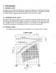
2. PERFORMANCE 2-1 MAXIMUM OUTPUT The maximum ouput of anengine is such standard power asdeveloped by the engine, after its initial break in period with all the moving parts properly worn in, when operating with a fully open throttle valve. Therefore, a new engine may not develop the maximum outputin the beginning because the moving parts are not in a properly worn-incondition.
PERFORMANCE CURVES MODEL EY28D, 288 PERFORMANCE CURVES MODEL EYZOD I ) for B t v m 5 1 .o Max. Toraue 4 3 HP .L B w r 2 2 1 2000 3000 2000 3000 4000 ( 1 000) ( 15001 I20001 4000 r.p.m. r.p.rn. Revolution Revolution 3. FEATURES 1. Compact, lightweight, durable, powerful 4-cycle air-cooled engine embodying ingenious design t e c h q u e s and skilful workmanship. 2. Simple construction, smart appearance, maximumeasiness of start owing to automatic decompression device 3 .
4. GENERALDESCRIPTION of ENGINECONSTRUCTION 4-1 CYLINDER, CRANKCASE The cylinder and crankcase are single piece aluminum die casting. The c y h d e r liner, made of special castiron, is built into the alminum casting. The intake and exhaust ports are located on one side of the cyhder, and are also inserted into the casting. The crankcase is separable on the output shaft side, where the main bearing cover is attached to it. (See Fig. 1 .) 4-2 MAIN BEARING COVER Fig.
4-3 CRANKSHAFT The crankshaft is forged of carbon steel, and the crankpin is induction-hardened. It has a crank gear premred-fitted on the output end. (See Fig. 5 . ) . "he EY 15B type has a built-in drive sprocket. (See Fig. 6 . ) Induction Hardening (Portion of Crankpin) Crank Gear (Pressure-Fit) Drive Sprocket - Fig. 6 (E Y 158) Fig. 5 4-4 CONNECTING ROD, PISTON and PISTON RING The connecting rod is forged of aluminum alloy, which itself serves as bearings at both the large and small ends.
4-5 CAMSHAFT In the D type, the camshaft is integrally built with a cam gear of special cast iron, and has intake and exhaust cams. Also the camshaft has aluminum plain bearings attached to bothends. (No ball bearing is used.) (See Fig. 8.) In the B type, the camshaft is made of carbon steel, and EYlSB type has a pressured-fitted cam gear and a driven sproket. (See Fig. 9.
4-7 CYLINDER HEAD The cylinder head is an aluminum die casting, and forms a Ricardo type combustion.chamber with amplearea for high combustioneffeciency.Thesparkplug is tiltedforeasy mounting of the fuel tank. (See Fig. 11.1 Fig. 1 1 4-8 GOVERNOR The governor is a centrifugal flyweight type which permits constant operation at the selected speed against load variations. Governor gear is installed on the bearing cover without fail, and it engages with the cam gear afterreassembling. (See Fig. 12.
4-9 COOLING The cooling fan serving also as a flywheel cools t h e c y h d e r and cylinder head by forced air cooling. Cylinder baffles and head cover are provided for guiding the c o o h g air. 4-10 LUBRICATION The rotating and sliding parts are being lubricatedby scooping and splashing the oil in the crankcase with the oil scraper attached to the connectingrod. (See Fjg. 13.) Fig. 13 4-11 IGNITION The ignition system is a flywheel magneto type with ignition timing set at 23" before TDC.
D m 4-12 CARBURETOR A horizontal draft carburetor is employed. It has been care- fully set after thorough tests to assure satisfactory start up, acceleration, fuel consumption, output performance etc. For construction and order details, refer to the Section on Carburetor Construction, Disassembly and Reassembly. (See Fig. i6.) Fig. 16 4-13 AIR CLEANER The air cleaner of the standard type type using asponge engine is an oblong element.
4-14 SECTIONAL VIEW OF ENGINE 4-14-1 MODEL EY15D Cylinder Head Blower Housing Ignition Coil Piston Pin Flywheel (Cooling Fan) Starting Pulley Governor Recoil Starter MODEL EY15D (BREAKER POINT IGNITION TYPE) - 10 -
\ I i /-Speed Control Lever Air Cleaner Piston Stop Button 'Carburetor .Muffler .
4-14-2 MODEL EY15B Cvlinder Head Spark Plug Cap Blower Housing Ignition Coil Spark Plug Piston Pin Flywheel (Cooling Fan) Piston Ring Crankcase Chain Guide Crankshaft Main Bearing Cover Starting Pulley Recoil Starter LGovernor --/ MODEL EY15B (SOLID STATE IGNITION TYPE) - 12 -
Fuel Tank 1 I \ Speed Control Lever Piston Air Cleaner Stop Button Carburetor Muff Ier Intake and Exhaust Valve Connecting Rod Tappet Chain Oil Scraper MODEL EY15B - 13 - r
4-14-3 MODEL EY20D Cover Recoil Starter Governor MODEL EYPOD (BREAKER POINT IGNITION TYPE) - 14 -
Speed Control Lever Piston Air Cleaner Stop Button Connecting Rod Carburetor Oil Scraper Camshaft .
4-14-4 MODEL EY28 ,Spark Plug Cap Spark Plug Flywhe Piston Ring Crankcase l g Cover -Governor MODEL EY28 (SOLID STATE IGNITION TYPE) - 16 -
Fuel Tank -0 I Intake and Exhaust Valve Tappet MODEL EY28 - 17 -
PREPARATIONS and SUGGESTIONS When disassembling theengine,remember well the locations of individual parts so thatthey can be reassembled correctly. I f you are uncertain of identifying some parts,it is suggested that tags be attached to them. Have boxes ready to keep disassembled parts by group. To prevent missing and misplacing, temporarily assemble each group of disassembled parts. Carefully handle disassembled parts, and clean them with washing oil. Use the correct tools in the correct way.
Part No.
5-3 HOW TO DISASSEMBLE *Length of the bolt indicates the length from the bolt head bottomsurface to the threaded end. I Order 1 Item Procedures Remarks I : Drain plug (1) Drain engine oil. Drain plugs on both sides of the crankcase. Recoil starter (1) Remove the recoil starter. 6@x 8 mm Flange bolt: 4 pcs. Be careful not to lose the gasket.
Item Order Remarks Procedures Tool ~~ ~ 3 Blower housinl (1) Remove the Blower housing from the crankcase and head cover. EY15,20 . . . 64 x 12 mm bolt: 2 pcs. 6q5 x 14 mm bolt: 2 pcs. EY28 . . . . . . 6q5 x 12 mm bolt: 4 pcs. 4 Fuel tank and head cover (1) Close the fuel cock. (2) From the carburetor disconnect the fuel pipe between the fuel strainer and carburetor on the side of the fuel strainer. (3) Remove the fuel tank from the cylinder head. EY15,20 . . . 64 nut: 2 pcs. EY28 . . . . . .
Order I Item Procedunx Remarks 8 Governor lever and the relative parts (1) Remove the governor lever from the governor lever shaft. 6$1x 25 mm bolt: 1 pce. (2) Remove the governor rod and rod spring from the carburetor. 9 Carburetor (1) Remove the carburetor from the cylinder portion of thecrankcase. Just loosen the bolt, unnecessary to take out the bolt. 1 Tool 10 mm box spanner or 10 mm spanner ~ ~~ Lever Fig.
Order I I Rocedu~s Item " 10 Starting pulley Remarks Flywheel (1) Remove the flywheel from the crankshaft Fit the flywheel pull- Flywheel puller er as shown in Fig.20, turn the center bolt clockwise and pull out the flywheel. (1) Remove the ignition plug cap from the ignition plug; and remove the i p t i o n coil from the crankcase. 64 x 25 mm bolt: 2 pcs.
Order 13 Remarks Procedures Item (1) Remove the spark plug from the Spark plug I Tool 21 mm box spanner cylinder head. ~~ ~~ ~~ ~~ 14 Cylinder head (1) Remove the 8 mm bolt and remove the cylinder head from the crankcase. 89 x 40 mm bolt: 8 pcs. (2) Remove the cylinder headgasket from the crankcase. 15 Intake and exhaust valve (1) Remove the inner and outer tappet covers from the crankcase. 69 x I 2 mm bolt: 2 pcs. ( 2 ) Pull out the intake and exhaustvalve.
Oil Seal Guide Main Bearing Cover J L Fig. 21 F&. 22 (1) Remove the camshaft from the crankcase. ~ 18 ~~ ~~~~ ~~ ~~~~~ (1) Remove the tappets from the crankcase. Tappet 9 -1 Intake Valve, Tool Remarks Procedules To prevent the tappets from falling or damaging, place the crankcase on t h e side. (See Fig. 23.) ~ Before removing put a mark of intake or exhaust on each tappet. In the EY 15B type, remove the tappets after step 2 1 .
Order (1) Scrape off carbon and other foreign de- I Piston and piston pin 20 I I Connecting rod and piston 19 Remarks Procedures Item I posits from the upper parts of thecylinder and piston, and then straighten out the bent tabs of the lock washers on the connecting rod, and remove two pieces of the bolt. ( 2 ) Remove the oil scraper, lock washer and connecting rod cap from the crankshaft.
5-4 HOW TO REASSEMBLE .Precaution in reassembling Every and each part should be cleaned thoroughly. Especially, pay utmost care and attention to the cleanliness of the piston, cylinder, crankshaft, connecting rod and bearings. Scrape completely off carbons from the cylinder head and the upper part of the piston; especially the carbon adhered in the groove of the piston ring should be carefully and completely taken out. Carefully check the lip portion of every oil seal.
3) DIMENSIONS of CRANKSHAFT PIN D (Crankshaft pin Dia.) PISTON RING GAP 0.090L - 0.135L 0.050L - 0.01 OL - 0.065L - 0.065L PISTON RING SIDE CLEARANCE IN GROOVES OIL R I N G - DIA. CONNECTING ROD TO CRANK PIN SI DE 0.063L 0.1 L CONNECTING R O D T O P I S T O N P I N 0.01OL PISTON PIN T O P I S T O N 0.009T - - - 0.09OL 0.095L 0.050L 0.01OL 0.020L - 0.065L 0.01OL - 0.046L 0.037L 0.3L 0.029L 0.
54-3 PISTONand PISTON RING 1) If no ring expander is available, install the rings by placing the open ring ends over t h e first land of the piston and spreading the rings only far enoughto slip them over the correct k g grooves. NOTE: Pay attention not to break the rings by twisting. Install the oil ring first followed by the second ring and then top ring. Meantime, the surfaces of the second ring and the top ring with carved marks are t o be faced up. I Ring Piston I I Fig.
3) When installing theconnecting I rod into place, hold piston rings with the ring guide as shown in Fig. 30 (if no ring guide is available, keep pressing the piston rings with finger tips and gently strike the top of the Piston Ring Guide piston with a wooden piece or the like to push it in), @or mark MA on the conand check that the symbol necting rod is in the direction of the flywheel magneto.
5-4-5 TAPPET and CAMSHAFT Insert the tappets back into their holes first, and then mount the camshaft. NOTE: Align the timing mark a t the root of a tooth of the cam gear with the one on the crank gear. If thevalve timing is wrong, the engine cannot operateproperly or a t all. (See Fig. 32.) In the EY158, set thewhite link plate a t the sprocket’s timing mark. (See Fig. 27.
NOTE: When installing main bearing cover, apply oil to the bearingand oil seal lip. Fit the oil seal guideover the crankshaft or camshaft lipfrom damage. to protect the oil seal Thenplacethemainbearing cover on. Check the crankshaft and camshaft their side clearanceare 0 - 0.2 mm; and if not adjust them with theadjusting Fig. 36.) (In D type, shims. (See adjustment of the camshaft is not necessary) Fig. 36 I NOTE: Main bearing cover tightening torque: ...... ... .. ...... EY15, E Y 2 0 .
5-4-7 I N T A K E a n d E X H A U S T V A L V E S Remove carbon and gum depositefrom the valves, valve seats, intake and exhaust ports and valve guides. NOTE: If the valve face is dinted or warped, replace t h e valves w i t h n e w ones. NOTE: If there is an excessive clearance between the valve guide and valve stem, replace the valve guide with a spare. F o r re- placing, pull out the valve guide, using the valve guide pulling base and bolts as shown in Fig.
5-4-8 TAPPET ADJUSTMENT Lower the tappet all the way down, push the valve, and insert a feeler gauge between the valve and tappet stem to measure the clearance. (See Fig. 40.) NOTE: The correct tappet clearance for both intake and exhaust valves is 0.1 mm * 0.02 mm as measured when the engine is cold. Spring Valve Valve Exhaust Intake, vT/ Grinding Face i .. I - Spring Retainer Tappet Fig. 41 Fig.
54-9 CYLINDER HEAD I I particularly its combustion chamber, and make clean the cooling fins.Also check Remove carbon from the cylinder head, the head for distortion. NOTE: Replace the cylinder head gasket with a new one. NOTE: DlSTlNGTlON between the GASKET ofEY15, EY20and EY28 The pitch of the holes for the bolts fastening cylinder head and the outer circumference dimensions of the gasket for EY15 and EY20 are same. However, the inner dimensions are different each other.
2) After measuring the air gap between the ignition coil . /" and flywheel, retighten the ignition coil. (See Fig. 45.) Air gap: 0.5 mm 1 \ \ I Fig. 45 5 4 - 1 2 CARBURETOR To the cylinder portion of the crankcase. install in the order of thegasket, insulator, gasket and carburetor, and then mount the air cleaner and fasten with two pieces of 6 mm nut. 54-13 GOVERNOR LEVER When reassemblying, refer to the7 . GOVERNOR ADJUSTMENT.
6. MAGNETO 6-1 MAGNETO The spark for ignition is furnished by a magneto assembly. The magneto consists of a flywheel, ignition coil and contact breaker assembly (including condenser), of which flywheel is mounted on crankshaft and ignition coil contact breaker are mounted in crankcase directly, The EYl5B type engine normally incorporates a solid state ignition system (T.1.C) described in 6-5.
6-3 TIMING ADJUSTMENT (See Figs. 47,48 and 49) The spark is timed to occur at 23” before the piston reaches TDC on the compression stroke. This spark advance of 23” is controlled by the breaker point opening and tius advance is obtained when the breaker point opening is adjusted according to the BREAKER POINT ADJUSTMENT to its proper point gpening. However, the advance timing is more accurately ad- justed through the following procedures using a timing tester as shown in Fig. 48.
Remove the flywheel without turning crankshaft at all. Loosen the lock screw of the breaker point support plateso that the breaker point canbe rotated. By rotating the support plate of the breaker point, fmd the exact point when the buzzer within timing tester starts ringmg from being silent. (SeeFigs. 48 and 49.) Put the flywheel back and check by rotating flywheel slowly. If the buzzer in timing tester starts ringing when line mark on the flywheel is in the line with line mark on the crankcase.
7. GOVERNE Models EY 15, EY20 and EY28 employ a centrifugal flyweight type governor. The governor is mounted on the governor gear and the throttle valve of the carburetor is automatically regulated by a lever which is connected to the governor in order to maintain constant engine speed against load variations. The adjustment procedure of the governor is as follows (See Figs. 50 and 5 1.
5 ) With a screwdriver in the groove of the governor shaft, turn it 'clockwise" fully until the governor shaft no longer moves, and then lock thegovernor lever to the governor shaft with the governor lever tightening bolt. (See Fig. 53.) Governor Lever Fig.
8. CARBURETOR 8-1 OPERATION and CONSTRUCTION (See Fig. 55 and Fig. 56.) 8-1-1 FLOAT SYSTEM The float chamber is located just below the carburetor body and, with a float and a needle valve, maintains a constant fuel level during engine operation. The fuel flows from the fuel tank into the float chamber through the needle valve.
8- 1 - 2 PILOT SYSTEM The pilot system feeds the fuelto the engine during idlingand low-speed operation. The fuel is fed through the main jet to the pilot jet, where it is metered, and mixed with the air metered by.the pilot air jet. The fuel-air mixture is fed to the engine through the pilot outlet and the by-pass. During engine idling, the fuel is mainly fedfrom the pilot outlet. 8-1- 3 MAIN SYSTEM The main system feeds the fuelto theengine during medium- and high-speedoperation.
8 - 2 - 1 THROTTLE SYSTEM 1) Remove the Philips screw (27) and throttle valve (22), and pull out the throttle shaft (23). 2) The spring (24) can be taken out by removing the throttle stop screw (25). *Exercise care not to damage throttle valve ends. 8 - 2 - 2 CHOKE SYSTEM and pull out the choke shaft (1 6 ) . 1) Remove the Philips screw (14) and choke valve (1 9 2) When reassembling the choke shaft, make sure that the cutoutin the choke valve faces the main air jet.
9. BREAK-INOPERATION An overhauled engine must be operated of REASSEMBLEDENGINE at low speed break-in the parts. A thorough break-in is indispensable particularly when the cylinder, piston,:piston rings or valves are replaced with new ones. The recommended break-in schedule is shown below. LOAD EY28 EY15 I I I SPEED EY20 NO LOAD 2,500 rpm 10 minutes NO LOAD 3,000rpm 10 minutes NO LOAD 1.35 HP 2.7 HP 1 I TIME CRANKSHAFTREV.) 1.75 HP 3.5 HP I I I rpm 3,600 I I 2.75 HP 5.
10. ROBIN SOLID STATE IGNITION ENGINE ('F.I.C. and P.I.T.) r 10-1 FEATURES Model EYl5D and EY20D can employ as option a pointless ignition system, called Solid State Ignition, w h c h is the circuit breaker type ignition device, utilizing the power transistor as an element for controling eiectric current. There are two types of this system, the one is outer coil type without pulser and is called T.I.C.(Transistor ignition circuit type) and the other type has a built-in pulser coil andis called P.I.T.
11. TRQU The following three conditions must be satisfied for satisfactory engine start. 1. The cylinder filled with a proper fuel-air mixture. 2. An appropriate compression in the cylinder. 3. Good sparks at the correct time to ignite the mixture. The engine cannot be started unless these three conditions are met. There are also other factors which makeengine start difficult, e. g.
11-1-3 ELECTRICAL SYSTEM Check the following for lackof sparks. 1) Leads of the ignition coil, spark plug or contact breaker disconnected. 2) Ignition coil damaged and shorted. 3) Spark plug cable wet or soaked with oil. 4) Spark plug dirty or wet. 5) Spark plug electrode gap incorrect. 6) Spark plug electrodes in contact with each other. 7) Contact breaker points pitted or fused. 8) Breaker arm stuck. 9) Condenser leaking or grounded. 10) Incorrectsparktiming.
11-5 ENGINE KNOCKS 1) Low-quahty gasoline. 2) Engine operating under heavy load at low speed. 3) Carbon or lead deposits in the cylinder head. 4) Sparktimingincorrect. 5) Loose connecting rod bearing due to wear. 6) Loose piston pin due to wear. 7) Causes of engine overheat. 11-6 ENGINE BACKFIRES through CARBURETOR 1) Water or dirt in gasoline, or low-grade gasoline. 2) Intake valve stuck. 3) Valves overheated, or red-hot carbon particles in the combustion chamber. 4) Engine cold.
12. INSTALLATION , - Engine life, ease of maintenance and inspection, frequency of checks and repairs, and operating cost all depend on the way in whch the engine is installed. Carefully observethe following instructions for installing the engine. 12-1 INSTALLING When mouhting the engine, carefully examine its position, the methodof connecting it to a load (machine), the foundation, and the methodof supporting the engine.
12-5 WIRING RECOIL STARTER OPERATION Wire as shown in the wiring diagram below. Normally, those indicatedby dotted lines are not includedin engine wiring. Lighting coil for Models EY15,.EY20 and EY28 (anoptional, not standard accessory) permits installation of an AC buzzer with an intermediate tap. [BREAKER POINT IGNITION TYPE] Condenser Ignition C o i l 2 m 3 - n ? m P v) Magneto Fig. 61 [SOLID STATE IGNITION TYPE for MODELS EY15 and EY201 1. T. I.C. (Standard) 2. (with P. I.T.
[SOLID STATE IGNITION TYPE for MODEL EY28l c 1. T. I.C. (Standard) Stop Button Ignition Coil Spark Plug l- Connecter Black rrm Exciter Coil (Option) Flywheel Fig. 64 [ELECTRIC STARTER TYPE for MODEL EY281 Key Switch Ignition Coil Unit Black S r----- I"" 7 7 h Battery (12V 24AH) Starting Motor /"- Fig.
13. ELECTRIC SBA TBNG MOTOR (OPVBO for EV28 ONLY) 13-1 SPECIFICATIONS Starting Motor Part Name Maker Denso Nihon Bolt K . K. Voltage 12v output 0.6 kW Weight 3.0 kg DriveLever Stop Collar Fig. 66 13-2 OPERATION Connect the (t) side of battery to the 8 $ terminal of starting motor magnet switch.
14. RECOIL STARTER DISASSEMBLY and REASSEMBLY The recoil starter hardly has a trouble in the normal use, however, case in it has a trouble or at thetime of lubrication, perform disassembly and reassembly in thefollowing procedures: Tools to be used: Box spanner (spanner), Cutting pliers (pliers) and Screw driver 14-1 HOW TO DISASSEMBLE (DType) Starter Remove the recoil starter from the engine with a box Rope spanner. Pull the starting knob and pull out the starter rope for 30 to 40 cm.
b 4) Take out the reel from the starter case as shown in Fig. 70: In this case, slowly take out it turning the towardleftand right so thatthe reel lightly spring is removed from the reel hook section. If the reel is suddenly taken out, there is a fear that the spring jumps out in the form as it is hooked, w h c h is very dangerous,so be carefuly of it. (If the spring jumped out, house itin the starter case as I instructed in Fig. 75.
3) Before puttingthe reel in the startercase,windthe starter rope in the arrowhead directionas shown in Fig. 73, and at 2.5 windings take out the rope from the reel notch. Set the reel hook to the inner end of thespring, and put the reel in the startercase. (At this time, confirm that the reel hook is duly set to the spring.) Then, hold the starter rope as shown in Fig.
14-3 CONFIRMATION ITEMS AFTER REASSEMBLY (Type D) 1) Pull the starting knob 2 or 3 times, and pull out the starter rope a little. i) If the starting knob is felt heavy t o pull and cannot be pulled, check whether the parts were reassembled correctly as instructed. n) If the ratchet does not function, check whether thespring is hooked properly. 2) Pull the starting knob, and pull out the starter rope all the way long.
15. CHECKS and CORRECTIONS P After disassembling and cleaning the engine, check and repair, if necessary, according to the correction table. The correction table applies whenever the engines are repaired. It is important for the servicemen t o be familiar with the contents of this table. Correct maintenance is recommended by observing the correction standardsspecified. The meanings of the termsused in the correction tableare as follows: Correction Repair, adjustment or replacement of any engine parts.
16. TABLES OF CORRECTIONSTANDARDS I ENGINE MODEL ITEM Flatness ofcylinder head I 1 Bore Roundness Valveguide I.D. Less than 0.1 EY 15 S.T.D. 63 dia. EY 20 67 dia. EY28 S.T.D. 75 dia. EY15 EY20 EY 28 Cylindricity STANDARD SiZE EY20 EY28 EYl5 EY 20 EY 28 0.01 Valve seat contact width 1 1 . Dif. between - rnax. & rnin. 0 +0.019 USE LIMIT 7 0.15 0.1 5 REMARKS 0.65 1 TOOL plate, CORRECTION METHOD Correct I Boring 1 0.01 5 EY 15 I 1 EY15 EY20 EY 28 6.5@ I O.D.
d Clearance between pirition ring and ring groove 1 1 EY15 EY20 EY28 EY28 TEY15 10-0.029 0.01 0-0.065 0.01 0-0.065 0.15 0.1 5 -0.009-0.010 0.06L 0.06L 1.5 1.5 -0.1 -0.1 - 0.04 -0.04 0.1 0.1 EYZO I 1 nd LIMIT REMARKS I 0.050-0.090 Ring gap 1 Ring I 1 dia. EY28 Large end I.D. Clearance between rad large end I.D. and crankpin Oil 2nd 2; Oil 2.8 T 0.20 - 0.40 0.05 - 0.25 0.1 - 0.3 Top 1.5 2nd 1.5 Oil 3.0 4.010- 24 dia. EY 2620 die. EY 28 28 dia.
ITEM lAODEL 24 die. CORRECT1 N LIMIT TOLERANCE 1 EY28 EYt5 EY20 EY 28 1 28 dia. 0.1 5 Micrometer 0.5 Re-machine or Replace -0.020 -0.033 Less than 0.005 Micro. meter Crankpin O.D. cylindricity Less than 0.005 Micrometer Crankpin O.D. parallelism Less than 0.008 Dial wuge Crankpin 0 . D roundness CORRECTION METHOD -0.037 -0.050 Crankpin O.D. TOOL Drive s. 25 die. EY15 Mag. 8 . 25 dia. Crankshaft journal O.D. Drive s. 25 die. EY 20 Mag.s. 25 die. - O.OO3 - 0.012 - 0.05 - 0.
ITEM 1 CORRECT1 STANDARD ENGINE MODEL I N TOLERANCE SIZE LIMIT USE LIMIT -0.15 Clearance between stem and guide - EY15 Intake Exhaust 0.056 0.025 EYrn EY 28 Intake Exhaust 0.025 0.056 -- I REMARKS CORRECTION METHOD Micrometer Replace Cylinder gauge Replace Feeler gauge Correct " 0.062 0.100 0.062 0.100 0.3 0.3 At middle blow When cold 0.10 *0.02 Clearance between groove and retainer I I I Stem end length - EY15 I EY,5 EY2O I I 0.1 Intake Exhaust 5.
tTEM Max. output Continuous Rated Output MODEL HP/rpm CORRECTION LIMIT EYISD EYl5B EY2OD EY28D EY 288 3.514000 3.512000 5.0/4000 7.514000 7.512000 Below 110% of rated output EY15D EYl58 EY2OD EY 28D EY28B 2.713600 2.711 800 3.513600 5.513600 5.511 800 ITEM Fuel Consumption ITEM Lubricant Consumption ITEM liter/hr REMARKS MODELCORRECTION PRECISENESS EY15 EY20 EY28 1.1 1.2 2.7 MODEL cc/hr USE LIMIT cc/hr EY15 10 50 EY20 EY28 15 60 MODEL Q EY15 EY20 0.6 EY28 0.
ITEM FREOUEMCYOFOILCHANGE EY15 EY 20 EY 28 Oil C h a w ITEM First time: Change oil after 20 houn operation. Second Time and Thereafter: Change oil every 50 hours operation.
17. MAINTENANCE and STORING & - m e following maintenance jobs apply when the engine is operated correctly under normal conditions. The indicated maintenance intervals are byno means guarantees for maintenance free operations during these intervals. For example, if the engine is operated in extremely dusty conditions, theair cleaner should be cleaned every day instead of every 50 hours.
17-5 EVERY 500- 600 HOURS(SEMIANNUAL) CHECKS and MAINTENANCE Checks and maintenance Remove cylinder head andremove carbon Reasons for requiring them The engine w l ibe out of order. deposit. Disassemble and clean carburetor. 77-6 EVERY 1000HOURS (YEARLY) CHECKS and MAINTENANCE Reasons for requiring them Checks and maintenance Perform overhauls, clean, correct or replace The engine output drops andbecome out of order. parts. Change piston rings. Replace fuel pipe once year.
Industrial Engines