
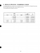
Specifications
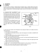
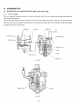

Remove the flywheel without turning crankshaft at all.
Loosen the lock screw of the breaker point support plate
so
that the breaker point can be rotated.
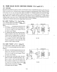
By rotating the support plate
of
the breaker point, fmd the exact point when the buzzer within timing tester starts
ringmg from being silent. (See Figs.
48
and
49.)
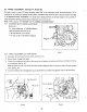
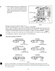
Put the flywheel back and check by rotating flywheel slowly. If the buzzer in timing tester starts ringing when line
mark
on
the flywheel is in the line with line mark
on
the crankcase. When the line marks are in alignment, the timing
is correct.
If the timing mark lines are not in alignmnent, then readjust the point opening according to the
BREAKER
POINT
ADJUSTMENT, by removing the flywheel and repeat the checking procedure
3)
through
5).
After completing the timing adjustment remount the blower housing and connect the coil primary lead to the stop
button.
MAGNETO TROUBLE SHOOTING
When the engine does not,start
or
starts with difficulty, or when its operation is unstable, the following tests will clarify if
they are caused by
a
defect
in
the magneto.
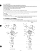
1) Check igntion cable for possible corrosion, broken, worn insulator or loose connection.
2) Check the sparking as described later in this section.
3)
Check if the breaker points require cleaning, or adjusting
or
not. If the points are badly corroded or pitted, condenser
may have to be replaced too.
Refer to ‘BREAKER POINT ADJUSTMENT.”
4)
If no spark takes place, replace igntiion coil.
*SPARK
TESTING
Remove spark plug from cylinder head and place it on blower housing, with the ignition cable connected to it.
Crank the engine several times by starting pulley and observe the spark
in
the spark gap of spark plug. If the spark is
strong, the ignition system can be eliminated as the source
of
trouble.
If the spark is weak or there is
no
spark at all, repeat the checks according to the procedures 1) through
3)
above.
The correct electrode gap is
0.6
-
0.7
mm. (Refer to section
“15.
CHECKS
and
CORRECTIONS.”)
6-5
SOLID
STATE
IGNITION (See Section
10
“ROBIN
SOLID
STATE
IGNITION ENGINE”
for
details.)
The following solid state ignition systems are available as optional or standard:
1) T.I.C. (TRANSISTOR IGNITION CIRCUIT)
(EY15,
EY20, EY28)
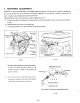
On the outside
of
the flywheel, an igntiion coil is installed, which is so-called outer coil type. This is equipped to the
standard type engine, and the exciter coil (primary-excitation) is available as an optional part. (The flywheel is for
common use.) (See Fig.
59.)
2) P.
I.
T.
(PULSER IGNITION TRANSISTOR) (EY 15, EY20)
The ignition coil and lighting coil are installed inside the flywheeel. Thls built-in type ignition system is installed to
the engine in whch lighting coil is requested. (P.I.T. unit is installed on the outside of the flywheel,)
-
39
-