
Specifications

7-3-3
FOR
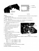
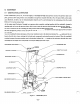
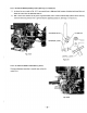
TIMING ADJUSTMENT, THE FOLLOWING PROCEDURES USING A TIMING,TESTER:
Disconnect the stop button lead wires and the coil primary wire.
Remove blower housing from engine.
Connect the timing tester lead with red rubber cap to
the coil primary wire and ground the lead with black
rubber cap to crankcase. (See
Fig.
7-3-3.)
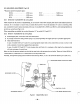
While the
points are open, the buzzer within tester remains ring-
ing and when the points are closed, the tester remains
silent.
Turn flywheel slowly counter-clockwise (D type and
V
type engines) or clockwise
(B
type engines) until the
buzzer within tester becomes silent.
Then, turn flywheel very slowly clockwise
(D
type and
V
type engines) or counter-clockwise (B type engines)
and stop immediately the moment the buzzer within
TIMI
\
GROUND
WIRE
tester begins ringing.
Fig.
7-3-3
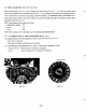
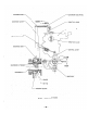
Check
if
line mark
on
the flywheel
is
in
the line with line mark on the crankcase. When the line marks are in alignment,
the timing
is
correct.
If the timing mark lines are not
in
alignment, then readjust the point opening according to the BREAKER POINT
AD-
JUSTMENT, by-removing the flywheel and repeat the checking procedures
3)
through
S).
Afer completing the timing adjustment re-mount the blower housing and connect the coil primary lead to the stop button.
MAGNETO’
TROUBLE
SHOOTING
When the engine does not start or starts with difficulty, or when its operation is unstable, the following tests will clarify
if
they are caused by
a
defect in the magneto.
1) Check ignition cable for possible corrosion, broken, worn insulator or loose connection.
2)
Check the sparking as described later
in
this section.
3)
Check if the breaker points require cleaning, or adjusting
or
not.
If
the points are badly corroded or pitted. Condenser
may have to be replaced.
Refer to “BREAKER P0IN.T ADJUSTMENT”
4)
If no spark takes place, replace ignition coil.
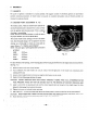
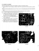
SPARK
TESTING
Remove spark plug from cylinder head and place it on blower
housing,
with the ignition cable connected to it.
Crank the’ engine several times by starting pulley and observe the spark in the spark gap of spark plug. If the spark is strong,
the ignition system can be eliminated as the source of trouble.
If the spark is weak or there is no spark at all, repeat the checks according
to
the procedures
1)
through
3)
above. The
The correct electrode gap is
0.5
-
0.7
mm.‘ (Refer to section
12.
CHECKS and CORRECTION.”)
-31
-