. Model
CONTENTS Title Section 1. SPECIFICATIONS 2. PERFORMANCE Page .................................... CURVES AC Output .......................................... 2 2-2 DC Output .......................................... 3 FEATURES 4. SERIAL and SPECIFICATION 5. SAFETY PRECAUTIONS .............................................. NUMBER LOCATION ................ 6 ..................................... 7 Fire Prevention .......................................
11. FUNCTIONAL CHECK Control 11-2 Stator..... 11-3 Rotor . . . . . lgnition Coil Condenser Rectifier . . 11-6 . ... . .. . .. . .. Panel DISASSEMBLY AND Preparation 12-1 12-2 Special 12-3 Disassembly 12-4 Assembly 12-5 Carburetor OF EACH . 11-1 11-4 11-5 12. Page Title Section . . . . . ASSEMBLY and Precautrons Sequence Procedure TROUBLESHOOTING 14. CRITERIA 15. WIRING 16. MAINTENANCE TABLE . . . . . . . .. Tools for Disassembly 13. COMPONENT.. . ... . . ... ..
1. SPECIFICATIONS Model Engine: i R600 Type Forced air-cooled, gas01 ine engine 4-stroke, Displacement 78 cc (4.76 cu.in.1 Fuel tank capacity 2 lit. (0.53 U.S. gal.) Oil pan capacity 350 cc (0.75 U.S. pints) side valve, L-- Ignition Solid state ignition system ~~ Starting Generator: Recoil starter system Rated continuous operating hours Approx. Approx.
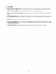
2. PERFORMANCE 2-1 Power CURVES AC OUTPUT Factor I . . . I I I 1 .o 1 ! I 1 I ’ ! 1 1 I I Output 1 OUTPUT’ Max. ............... 500W Rated ............... 400W Frequency. Voltage. i 3 w 3 -t , // 240 ................ .................. 50 Hz 220V FRECiENC I i/: Y ‘1 I i I I I 1 300 I t $ a CURRENT 50 i 1 I : I : I I, IA) - 1 , I 1 /‘\I I I 0.51 / / / I : 1: CURRENT I I I I I 400 2 t I 300 2.5 ............... 500W Rated .........
. . . . . . . . . . . . . . . 500W Rated . . . . . . . . . . . . . . . 400W Frequency . . . . . . . . . . . . . . . . . 50Hz Voltage . . . . . . . . . . . . . . . . . . . 11OV Output Max. w U LL 3 1 -1 w > U 1 a CURRENT ( A ) - 1 -I N tI 3 600 61 U 60 w LL 500 62 U 400 59 -1 3 I- 120 a 110 J 100 0 3 0 17 I- 1 I 300 w > 1 . . . . . . . . . . . . . . . 600W Rated . . . . . . . . . . . . . . . 500W Frequency . . . . . . . . . . . . . . . . . 60 Hz Voltage . . . . . . . .
600 Output 52 51 Max. ............... 500W Rated ............... 400W 500 Frequency ................. 50 Hz 50 .................. Voltage. 49 400 300 200 0 1 2 CURRENT 3 IA) 4 5 11OV t 3 + 3 E 2 6 - 1 I I I I I Output 62 Max. ............... 600W Rated ............... 500W Frequency ................. 60 HZ 61 400 60 59 FREQUENCY 300 r I 200 120 .................. Voltage. 11OV I 3 f k ‘0 110 100 100 0 0 1 2 3 CURRENT IA) 4 5 6 - Output Max.
3. FEATURES l Robin Exhaust Fan Cooling System for low body temperatures, low noise. longer engine life and reliable performance. l Large 78cc 4Stroke l Simple One-Touch Engine Control Switch with the engine and fuel on/off levers and choke all integrated into one Engine provides enough power for constant 500W (at 60 Hz) rated output. switch. l Easy and Reliable Starting with pointless ignition. This generator is also a brush-less type generator for maintenance-free operation.
4. SERIAL and SPECIFICATION NUMBER LOCATION The serial number is stamped on the crankcase at the opposite side of the carburetor. The specification and specification number are shown on the nameplate located on the rear cover. Always specify these numbers when inquiring about the eoenerator or ordering parts in order to get correct parts and accurate service. SPECIFICATION SPECIFICATION NUMBER SERIAL Fig.
” - . . . - . . - - 5. SAFETY- PRECAUTIONS 51 FIRE PREVENTION 1) Keep the generator away from combustible materials during operation. Take special precautions with flammable substances. 2) Do not run the generator in a incline position or while it is slanted at an angle. Avoid moving the generator while it is in operation to prevent the generator from falling over or leaking fuel. 3) Do not place a carton or similar object over the generator while the generator is running.
6. COMPONENT IDENTIFICATION h’UFFLE9 C 0 V E F1 AlFl Al= CLEdYER CLEALER CO\.‘ER Fig. 6- 7 FUEL T.
\*’ ” z FLER C:O\.‘ER / RECOIL STIRTE? Fig. 6-3 SPARK Ffg.
CAPBLRETOR Fig. 6-5 #El3 PIPE AIR \;E’JTl Fig.
7. FUNCTION 7-1 7-1-1 of EACH COMPONENT REAR HOUSING GENERATOR RECTIFIER STATOR The stator consists of a laminated silicon steel sheet core, a main coil and condenser coil which are wound in the core slots. AC and DC output are taken out from the main coil. (DC output is taken out from the part of main coil which is in the middle of the main coil.) The condenser coil excites the stator field coil which Fig. 7- 7 generates AC output in the main coil.
7-2 7-2-l ENGINE CYLINDER and CRANKCASE The cylinder and the crankcase of the engine are of an one-piece aluminum die-cast design. The cast iron cylinder liner is cast-fitted inside the cylinder. Both the intake and exhaust ports are positioned at the lateral side of the cylinder and these ports are formed by using a mold with die-cast cores. The crankcase has its joint face located on the generator side.
7-2-9 EXHAUST FAN COOLING SYSTEM Instead of blowing outside air on the engine. the Exhaust Fan Cooling System of this generator intakes the cool air and forces the hot air outside from one outlet. This keeps the body temperature lower for greater safety and extends service life. 7-2-10 LUBRICATION SYSTEM The moving and sliding parts inside the engine are lubricated with the oil scraper fitted on the connecting rod.
8. DESCRIPTION 8-1 ELECTRONIC OF MAIN COMPONENTS OPERATION IGNITION SYSTEM (Solid State Ignition System) The electronic ignition system features a polver transistor as the current control element. Therefore. the ignition system is an electronic contact point-free type that operates with the po\ver transistor impulses controlling the current. This system also called TIC (transistor igniter circuit) is virtually free of ignition failure which generally results from contamination of the contact points.
c 8-2 GENERATOR .I OPERATION INITIAL EXCITATION PERMANENT MAGNETO FIELD COIL ROTOR STATOR i : I RECEPTACLE RESIS ----- DIODE MAIN COIL CONDENSER COIL CONDENSER L ------ A Fig. 8-2 8-2-l 1) GENERATION of NO-LOAD VOLTAGE When the generator starts turning the permanent magneto built-in to the flywheel generates@ 1 to 2\’ of AC voltage in the main coil and also generates 1 to 4 of AC voltage in the condenser coil.
8-2-3 DC OUTPUT DC output is taken out from the main coil and is fed to the diode at which time the output undergoes full-wave rectification prior to being supplied to the load connected to the generator. The diode rectifier works to allow the current to tlow in @ direction but does not allow the current to flow in s direction as shown in Fig. S-3. Fig. 8-3 Fig. 84 shows the DC output circuit of the generator.
9. OPERATIONAL 9-1 AC LIMITS OF THE GENERATOR OUTPUT: Electric appliances normally have rating labels, showing the rated voltage. frequency. power consumption (input power). and other listings. The input power specified on such labels is what is required to drive the appliance. When an appliance is to be connected to the generator. the power factor. starting current. and other factors of the appliance must be taken into account. 9-l-l NET RESISTANCE LOAD: Incandescent lamps. electric heaters, etc..
9-l-4 IN THE SITUATION THAT POWER CONSUMPTION IS NOT SHOWN ON THE RATING PANEL: Occasionally. the rating panel of an electric appliance does not carry its power consumption but only shows the mechanical equivalent to the power consumption. involved. In such a situation. it is necessary to calculate the power consumption of the device Depending on the types of load. the calculated power consumption is adjusted according to paragraphs 9-l-l through 9-I-3 above.
9-2 DC OUTPUT When the generator is employed to recharge batteries. care must be exercised about the specific gravity of electrolk-te rn each batter\. case. 9-2-l MEASURING THE SPECIFIC GRAVITY OF ELECTROLYTE: The specific gravity changes with temperature; therefore. it is converted to another corresponding to 20°C. S20 = St + 0.
9-3 SIMULTANEOUS USE THE AC/DC OUTPUT If you use the AC’DC output simultaneously in this generator, be careful not to exceed the total power consumption. 50 Hz below 3OOW Hz below 3OOIV 60 NOTE: 9-4 Max. output WIRE of DC is 1OOW /12V x 8.3A). LENGTH When long Lvires are used between the generator and a load, the resistance of each wire increases and a voltage drop occurs. Consequently. the input voltage to the load declines and occasionall!- damages the load.
10. MEASURING PROCEDURES AC 10-l 10-1-l DC VOLTMETER VOLTMETER METERS VOLTMETERS Both AC and DC voltmeters are nesessar! . The approximate AC voltage ranges of the voltmeters to be used for various types of generators are as follows: 0 to 1SOV: Type with an output voltage of 110 or 12ov 0 to 300V: Type with an output voltage of 220.230 or 21OV Fig. 70-l 10-l-2 AMMETER AC Both AC and DC ammeters are necessary. AMMETER DC AMMETER The AC ammeter must have a scale range from 0 to approximately 10A.
10-l-4 CIRCUIT TESTER A circuit tester is used for measuring resistances and others. Fig. 104 10-l-5 MEGGER TESTER To measure the insulation resistance of the generator. Use voltage capacity of 5OOV. Fig. 10-5 10-l-6 TACHOMETER Use the contact-less tl pe tachometer. Fig.
10-2 MEASURING AC OUTPUT SWlTFf; TOACd+)@ LOAj km77 With the circuit shown in Fig.lO-7.measurement 1smade of the AC output of the generator. An electric heater or an incandescent lamp with a power factor of 1.O is suitable as a load for the generator. When the measured AC output of the generator is confirmed to be wnhin the voltage range specified in the table belon. over its voltage rating. the AC output is normal. Measurement must be made under rated load and at rated speed; sometimes.
10-4-1 STATOR Measure the resistances betlveen red coupler leading from the stator and the core. Fig. lo-10 1O-4-2 ROTOR d Measure the insulation resistance across one of the soldered terminals of the rotor and the core. Fig. 10-11 10-4-3 CONTROL PANEL Measure the insulation resistances between the live parts and the grounded part. If the measured resistance of a component is below 1MR. the insulation is defective.
-- 11. FUNCTIONAL 11-l 11-l-l CHECK of EACH COMPONENT CONTROL PANEL ENGINE SWITCH Using the circuit tester. check continuity across the black and green top terminals of the 6P coupler. When continuity between the termmals is confirmed with the engine switch turn2d off. the switch is normal. It is also normal if there is no continuity between thrse terminals, when the engine switch is set at RUN or CHOKE position. Fig. 11-l 1 l-l-2 FREQUENCY METER Also check with the circuit tester.
11-1-4 AC RECEPTACLES Using the circuit tester. check continuity between the t\vo terminals at the rear of the XC receptacles while the receptacle is mounted on the control panel. When continuity is confirmed between the output terminals of the receptacle Lvvltha \vtre connected across these terminals. the AC receptacle is normal. When the wire is removed and no continuity- is eonfirmed between these terminals. the receptacles are also normal. Fig. 7 7-4(A) 11-1-5 Fig.
11-2 STATOR Measure the resistance of each stator coil using the circuit tester. I Main coil : ! Classified coil For use with the frequency meter AC coil I I DC coil / I : Condenser coil I Cord color of @ Condenser coil I Measurement location 6P coupler j 6P coupler Rectifier connector 50Hz-110V 3.4R ’ 0.2251 1.1n 60Hz-110V 2.6 I 0.16 0.9 3.3 j 0.22 50Hz-120V j 2.7 60Hz-120V ’ I , 0.16 7.6 0.9 7.6 1.1 8.9 60 Hz - 220V 11.4 0.16 50 Hz - 230V 15.2 0.22 1.
FL?. 7 l-7 Fig. 1 l-8 Fi:g. 1 l-9 Fig.
Table 1 l-2 Fig. 11-11 NOTE 1: Measure the resistance 2: If the circuit of each coil winding while the diode and each resistor are disconnected with the/r solder removed. NOTE tester is not sufficiently accurate, it may not show the values given and may give erroneous read- mngs.
11-5 CONDENSER Measurement of capacity substitutes for checking the condenser. The capacity of the condenser cannot be measured by using the circuit tester. Therefore. the generator is run with a new condenser to see whether or not the generator performs normally. If the generator performs normall>-. the condenser is normal. Reference: If an instrument ii available for measuring the capacity of the condenser, the total capacity range should be 70 to 7 7pF fat 20°C).
- 12. DISASSEMBLY 12-1 PREPARATION *- and ASSEMBLY and PRECAUTIONS 1) Be sure to remember the locations of individual parts when disassembling the generator so that the generator can be reassembled correctly. Tie tags noted with the necessary information to facilitate easier and smoother reassembly. 2) For more convenience, divide the parts into several groups and store them in boxes. 3) To prevent bolts and nuts from being misplaced or installed incorrectly.
12-3 DISASSEMBLY SEQUENCE I Sequence Part to remove 1 Side cover (Lj and (Rj -I 3 I I Couplsrs (disconnection) I (1 j Remove both the left and right co\-2rs. by taking out eight 31-C flang2 screws. 1 (1) Disconnect th2 (6Pj coupler of the generator from the other (6P) extending from the control panel. ’ Choke cab12 II ! 4 Fuel line I 5 ’ Fuel tank handle I Precautions Description (1) Set the engine control to STOP.
Part to remove Sequence 6 8 ( 1) Remove the rear :over at the opposing sid2 of the control pan21by unscrewing th2 four $16 flange bolts. 1Omm box spannsr Fuel tank (.I) Loosen the set screw of th2 strainer shaft at th2 rear of the engine control switch. (2) Remove two M5 flange bolts clamping the front cover and tank bracket together. and tank bracket together. and then remove the fuel tank. ,z Plus screwdriver Front cover (.
Sequence 12 13 (1) Remove one set screw of the earth wire which grounds the rear housing and base plate togethsr (Zr)OV system onlv). (2) Rsmove four 5115x 10 bolts from under the base plate. Bas2 platz (1) Remove the recoil starter from the rear housing. by removing three 516 x 8 flange bolts. Recoil starter Starter pullek I I I (1 j Turn the starter pulley b]- hand to set the piston to the compression stroke limit (lvhere the pulle) becomes heavy).
Part to remove Sequence 16 Description ’ Rotor assembl) Precautions (1) Fit the rotor puller to th2 rotor shaft. and drive it into place to remove the rotor from the engine shaft. 1; Plug cap (1 j Remove the plug cap from th2 spark plug in advance. (3) Remove the clamp of the highvoltage power cable. 18 Front housing and center baffle (1 j Remove the front housing and center baffle from the engine main bearing. b) removmg thrze M6 x Xmm bolts and one M5 x 55mm bolt.
Part to remove Description Precautions 20 Governor and related parts (.1) Remove the governor lever from the governor shaft. (~j Remove the governor rod, rod spring. and governor spring. Loosen the bolt (unnecessary to remove it) ‘1 Carburetor (1 j Remove the carburetor from the stud area of the intake side flange of the crankcase.
Sequence Part to remove Description 28 ’ Camshaft (1) Pull out the camshaft from the crankcase. 29 ; Tappets I (1 j Remove the tappets from the crankcase. II Connecting rod ! and piston I I Piston and piston rings 31 I 32 Crankshaft (1 j Pull out the crankshaft from the crankcase. If unable to pull it out by hand, use a plastic hammer to gently strike the main bearing joint tace. and pull the crankshaft pulled out. 33 Governor shaft (1) Remove the clip of the governor shaft.
12-4 ASSEMBLY PROCEDURE 0 Precautions in Assembly 1) Thoroughly clean each part. When cleaning. take special care for the piston. cylinder, crankshaft, connecting rod, and bearings. 7) Be sure to completely remove the carbon deposits on the cylinder head and piston head. Also, thoroughly clean and remove carbon deposits from each piston ring groove. 3) Apply lubricating oil to the lip of each seal. Confirm that the lip of each oil seal is not damaged. If damaged, replace with new one.
l Tolerances of Newly Installed Parts Thrust directional tolerance between the cylinder and piston skirt I ! Top ring Clearance of piston Second ring joint I ring 0.008L 0.2L - 0.047L - 0.4L 0.2L - 0.4L Spare rings ’ Oil ring ! Top ring Clearance between piston ring Second ring 1 I Oil ring outslde diameter between connecting Clearance between piston 1 0.09OL - 0.135L 0.06OL - 0.105L Spare rings , 0.037 L - 0.063L I Side clearance Clearance - 0.25L O.OlOL-0.
STD EQUIPMENT - Top ring ! ’ Taper SPARE PARTS Taper I \ Second ring Taper Undercut ‘\ . \ ‘,\ x. :. q \ .. \ Oil ring I Fig. 72-72 1244 INSTALLING THE CRANKCASE 1) The connecting rod is put into the cylinder while GUIDE holding it with the piston ring guide. as shown in Fig. lo-13 (in the case that a piston ring guide is not available, press rings inward with fingers and at the same time. strike down the piston. using a wooden block).
12-4-6 INSTALLING THE TAPPETS and CAMSHAFT Install the tappets. and then the camshaft. NOTE: with Align the timing the timing mark is set incorrectly, ly. mark at the base of the cam gear of the crank gear. the engine If the valve timing will not run or operate proper- (See Fig. 72-75.) NOTE: If the reverse order, intake tappet and exhaust clearance valves are installed in will be incorrect. Fig.
*Shown in Fig. 12-18. is the method to measure the side clearance of the crankshaft. According to this method, measure the clearance between the machined face of the crankcase and the adjusting collar. The machined face of the crankcase is mounted with packing so it is necessary to set the clearance properly by allowing for a packing thickness of O.??mm. -I M6 x 25mm bolt . . . . . . . . . 8 PCS. M6 x 55mm bolt . . . . . . . . . 1 pc. Fig.
12-4-9 Set TAPPET ADJUSTMENT the tappet at 1112 loa-est position to depress the valve. Then measure the clearance between the valve and tappet stem. using a clearance gauge inserted into the clearance. (See Fig. 12-21.) NOTE: As with the intake and exhaust valves, the clearance between the valve and tappet INTAKE NCE & EXHAUST If the clearance is smaller 0.1 f. 0.02. VALVE VALVE SPRING GAUGE Fig. 12-22 Fig.
12-4-13 INSTALLING THE HEAD COVER The head cover is installed over each of the left and right parts of the c>-linder head. using the 345 x 1Omm screws. 124-14 INSTALLING THE GOVERNOR and RELATED PARTS Model EYOSD has a centrifugal iveight type governor which is installed while engaged with the governor gear. With the governor. the throttle valve of the carburetor is controlled automatically by using a lever link mechanism. Therefore.
. *. 124-16 INSTALLING 1j THE CENTER BAFFLE and FRONT HOUSING Set the knock hole of the front housing to the knock of the main bearing cover and assemblethem together. During assembly. place the center baffle between the main bearing cover and front housing. Torque for the front housing: 80 - 100 kg-cm 12-4-17 INSTALLING THE IGNITION COIL 1) Install the ignition coil and grommet (IG-COIL) to the front housing. Simultaneousl>-. temporarily set the generator rotor in position.
12-4-23 RUBBER TUBES for USE as AIR VENTS Connect two rubber tubes to the air vent connectors of the carburetor. Keep theje rubber tubes suspended downward from the air vent connectors. 12-4-24 INSTALLING THE BASE FRAME Install the base frame with its rear side facing the 1) welded nut area of rubber mount (A). Match the rubber mount (A) which is fitted to the lower part of the engine and generator. Base frame is installed using four MZ bolts.
3) Align the mounting holes at the lateral side of the front cover with those in the bracket which are bolted to the fuel tank. Then. install the fuel tank. using t\vo $16 x Emm flange bolts. 4) hlake sure that the flexible shait on the control dial side is inserted in the square hole of the strainer shaft. then fasten the flexible shait . 124-30 INSTALLING THE REAR COVER Align the mounting holes at the lateral side of the rear co\-er urth those in the fuel tank bracket. Then install the rear cover-.
12-5 CABURETOR 12-5-1 FUNCTION and COMPONENTS (See Fig. 12-28) 1) Float system The float chamber is located direct& under the carburetor. Flat and needle valves. maintain a constant id level inside the float chamber. The fuel in the tank tlo\vs into the float chamber from the needle valve. When a certain quantity of fuel enters the chamber. the float rises. When the buoyax)- oi the flat \-alve balances with the fuel in-flow pressure of the needle valves.
2) Pilot jet nozzle system The pilot jet nozzle system controls the fuel supply for engine speeds ranging from idle to low-speed running. The sytem operatzs with the fuel flowng through the main jet nozzle and up to the pilot jet nozzle where the tuel is measured. When the fuel is mixed with air. the volume of the air-me1 mixture is also measurzd by the pilot air jet. From this stage. the mixture is supphed to the engine t‘rom the pilot outlet and bb-pass. During idle.
5) Float system Pull out tloat pin (13) and remove float (I 1j and needle valve (,30). * Avoid using a drill or a wire to clean the fuel passages(they map damage the orifice of the pilot and main jet nozzles’). Use compressed air. * The float pin is peen-secured to the carburetor body; the needle valve and float can be removed out from the opposite side of the peen-secured part b>-lightly striking the float pin with a thin bar-like object. 27 / 24 1' 28 Fig.
13. TROUBLESHOOTING DIAG: 8 DIAGNOSIS 0 ?-) DIAGNOSIS BY THE CUSTOMER DIAG. 01 DIAG. 02 Engine fails to start. Electricity not generated. If the generator doesn’t perform properI>- or fails to run after troubleshooring. ask a qualified service dealer to check it. n DIAGNOSIS A. Fails 3) 4) 5) 6) 7) 8) 9) 10) 11) 12) 13) to start DIAG. DIAG. DIAG. DIAG. DIAG. DIAG. DIAG. DIAG. DIAG. DIAG. DIAG.
DIAG. 12 Engine fails start Check fuel quentity lo Engine fails to St;lrt Check fuel quality I 1 DIAG.
--- -. Sym(~lollls _. . .- P0ssil1lc CilllSCS ___-. I 8 I -_. _ ..-_- Ilclns -- -. -- J (‘hccking critcliil ._ Mcasurc dcglcc 111 lcvcl11css 10 check and proccdllt c 1 (‘heck -r -- .., . -_- I.ovet the service liillil -_ Ilie sclvicc liiiiil Over I - Not level ..- _--.. I,. I (Ilwck gaskcl -. .I.. lllc -r 1 -- end ol' wlve atljllsl n1ove sm00111ly lhc ;1nd IllC iappct Spa"" - ..] F .--(‘I~ill~ltlCC Lhlllil#Xi gasket OI ovcrst poke rmgc 1 . _. --.
-71 Ll DIAC. No I’ucl t’lows OUI CVCII wlwn Ill0 I’IICI pipe is diswrinccl- Syrnplorns . .-- -- -I .- -. -. ..- .-- _ ..- I ,-.--.. ..- IO cllcck atld [“‘occtlllrc L -_-- -_-. --. Chock IIN bolt 01 nihher pipe iri the Ilanlllc EXAM 3 I .- AlXllllllllilll1~l1 -.._ _. ..-_ L- I-- . . I .-. .-LVICi#Il or ICplilCe r .--. IL - --_ -_ Dcl’cclivc I’il~Cl I’ucl --_ --- - -- 1 1 (‘llcck - -- Sel in lhe closed posil ion -- _I _--.
rl Syl~lploms - --.I.--- (‘twk (Tly lo 111ovc) -._ --. I (‘heck __ ,_-. .,1 Measure the tloar hcighl.
-.-.. !I Synlplollls -.-....--._ I ._I. DIAC. 32 1 Engine opcr;il ion dmornial l.nbric:iting oil consunipt ion increases (gels thin) Excessive noise T' --."- L : Fuel Possihtc CBUSCS . . l r ..,.- it2 .-._..-. L-._ Li ‘1 Excessively worn sliding parts ((‘tlilllgC the oil) lJxcossivcly wortl sliding paris (llsc ol’old oil) -----I I Check 1tic COIUprcssioii To DIAG. IS or 16 IlilIlCC) _ .--.. r -. Check thcjel (Jut number, looseness) Cltlcck i._..
Sylllt~IolnS r: ,, ._-. Noise protlucctl and Lxccssivcly - --. ._ I..1 ('ICillNZr ot' C'Il1sw L 01 d;magc ltic piston 01 rod connecliiig .- __..-.. I j (‘llcck ‘, ..- ._- ,.- connecling ---I I .--.- (‘heck .- Rich - -. rJJixlurc 1 -- Cheek IIIC main jcl (i)r loosc~~css antI ,jct nlllnhcl To DIAG. ,.. .-- II>ii I rod I- I:ucl riiixctl wit I1 foreigli si~hsl;rnccs -- Repli\cc with normal I’ucl ;III~I cheek 2I .-..
Ll Hnginc Ir011hlc Excessively Wtlilc t’~jlllcs protlucctl Iqo luhricitlirig oil co~~suriiption --- ---- - _ -. _..--I -. r- VillVC 1Nll Possihlc WOlIl c;Iuscs Sticky Ollf WOrll I-- r and rctllln valve &,gglXl - III.' 1 .I- (Ihcck clcararicc pislon I .-- I -.-_. Cheek of (‘heck C’hcck --.-1 --- I -r -.
- ----I --.__.. _ ._-I I._ .- 7 11I MAC. 36 (‘or~lrot /XlIlCt rncler Ttlc pilot light I;lilS 10 light Op. Sylllptl~llls I;lilS IO StlOW the needle res(ilig . PiNlS 1 .. ._ Wilt hlc~kcll ‘lie OI tlc(‘cct ShCM 14 % I _, 1 IlClllS I I .__ lo clwk and ploccdurc ‘W Mci\llSrc the rcsislnncc (hl’ coiiplcr) !. .- wtlcll 41 ... Witc hlokw OS1 . . .
Vc~y low 01 rlotIIing? hginc is opcr;rtirrg well Mcasurc AC outpul EXAM I AC voltage Kerr1cdies I I MCISIJW AC output Measure DC OIII~UI EXAM 1 is low by .--- _ _.__-.. .,.. _. ,._-. _I_ To DlA(;. 40 I To DIAG 45 To INAG. 43 -ir To I)IAC.
--.,. --.DIAC,. 44 -. __..-_... _1 - The IX’ oulput vollagc is only SCYj% 01’ lhc ralctl value Sylllpllm .--.. - .-,L. L.-I 1 Slulor Stator IX1 coil ;7 main coil IXiltl --.. I Wire hrokcn shor INi OI - The diode r -I One diode is tlct’cctivc is def’cctivc -1 - Tile soldered pilrt is dcl’cclivc, ;rd ;rd the the lead is hrokcn 1 --I... - Measure Ihc rcsislcliodc terniinds Measure of the Circuil leslcr lcrniinas) ,.- Wllerl 42 ... When Wire blokcn WllCll OS2 . . .
--. --.-.... ..IN’%, higher or more IX: is output Symptoms . . r].-. l+rigirie running is high r1 -- i ..__ T -.A speed r ..,, .._- Possible -r lo Condenser -. - _-_- ._.--- McilstJre To DIAG. 52 C’hcck 111egovernor the (circuil tester hc li)r used DilTcrcnl (‘hecking criteria slilrltlad -_ ____ Replace Kcnicdies _-_-.--____ 1 r -_-- - L. - SlillOr tllilill coil -7’ coil coiidenser --- c;~ii nol (bclwccn this T OI I-z Mcasure capacily 1,, .
.-- ---‘-‘-r _._--..u ,1 c. .-.-.L..__.. --7 1 __--. A(: ,. OUllW1 VOlliIgC is only 20f% ol’ lhc ralcti value ._ ._ Pitrls Rotor ---I- I E I __ Mcasurc coil Aged or broken rotor _- 1 .-A-- 0I’Ihe The coil is shortcd The coil is shorted --_-_. llcn1s lo cheek and procedure hgine - Shorting Possible causes (lonclenser - ----‘T’ resistor _ -- -.
--- Sylllpll~llls ..I I T” Dcl’ective selliiig ol’ the governw lever illld level shnl’t .- --.-.. Possible C3IISCS ---- ! - _- -- Iiems --- ._-.. _ C’hecking CrilL’riil - -.,_ -- Dc~cctivc J ihc II~OVC- Check ihe set posil ion --- _-_. _ 1. .wiling nlixlurc I,eilll .._ (‘lwck lo CllCCk ;I1111 produie -. _..--I Poor or clcl’cclive perli)rmullcc I--L (‘llcck I hc I’ucl pipe of cnburctor -___. 1 KeplilCe -_ _ -. T ..-_.- - ----, _-,,-L-_- ._ _-.
DIAC. 52 Kngiiic speed --_--,n a ._.r1 .. 110CS illcreils~ no1 . .-.. 4 _ .--_ I I C’ilrburclor and ilir Valve t%?Clriciil cleaner load ..-,- -.-, -, --- ---_- I Possible C’I L 11scs __ Ikt’ecl ivc sell I -.- The irig liming ol’ ihe -1._...-.~ Mixture valves is tlcl’ectivc. --- and iiiul’ller is incorrect. / Ovill~;iillil .-._ -_. --- -. .,,_,--.- Cheek the carburator. t;XAM (‘heck lhc ;lirclenncr Check the SCIt ing ,,, ..--. I EXAM .
- _ --. ..-..---- -- -I -.....-I. -l.---..._ __I._--,_______ I 1I 1 L 1 r 1 J 1 --. _. _.. -r--- (‘ylimler rnul’fler Cylinder heiltl hind cylinder PiIrIS _. 1 -. .-. _. 1 .. __- ,... -._ 1 _- licad ldeclric Cnrburctor I _. I ---I-- ---I. l .__L-.-. Spark lid ___-_ .-- . . ._ .- .-.- .---- l -- plug -- i, ._- 1 I’ossib lc CiIlISCS . ) 8 I ,- I! - llcrlls (‘ooling I’;llls iIN! AClXllllllliltil~ll to Overloading ,, --.
I Poor pdorniancc No trutpu1 -. , No comprcssiou , L..- - .J L- -- Misfire or cond~~stion ou,side the Poor performnnce Backl’irc .-,--J L_-+ Worn out Possihlc point is dcl’cclivc _ -l -- CilllSCS I , .- .- -. ltcrlls -_ ! -.-.-r -. IO check and procetlul c Dcfccl ivc Rich niixlure. (‘onlacl C’hcck 1hr IappCl ClCilrilncc. Check tappet Ckiirancc.
14. CRITERIA TABLE for ADJUSTMENT Levelness of cylinder head Below 0.1 Seat width of Intake exhaust valves and 1 lnstde dia. of valve guide Piston skirt’s dia. I” thrust outs,de dIrectIon ’ I ’ Ring groove width Piston i 1 Cylinder 5.656 dia. Cylinder I gauge Slide calipers and cutter Center Repalr ’ Repair Replacement gauge I 0 -o,02 Micrometer 50.92 Replacement I 1.65 Slide calipers Replacement Second , ,5 ~0.025 0 1.65 Slide calipers Replacement 011 2.5 ao.
I I Items of adjustment I Criteria , limit of application Description Tools Ramarks I 1 Crankshaft Crankpm outside dia. 1 Crankshaft journal outside dia. , i I Micrometer Replacement Counter- , 7. -0.003 -0.011 ‘6.950 Micrometer Replacement 18.4%” 18.15 Micrometer ! Replacement 9.950 Mtcrometer ( Replacement 9.959 Micrometer Replacement Slide calipers Replacement Square Replacement Mtcrometer Replacement Micrometer Replacement &:erator ,O9-o.O’3 -0.028 : -0.
Items of adjustment (Tightening torque) 1 Connecting rod bolts I Main bearing [ Cylinder Spark cover bolts head bolts plug Air cleaner Governor nuts lever nuts I Front housing I Rotor bolts 1 Muffler I Front bolts Criteria 60 -80 Limit of application ’ Description ’ kg-cm 80-100 go-110 I 120 -150 I I 1 I 50 -60 I I 70 -90 I I I I 80-100 100-150 I nuts cover bolts Tools I 55 -75 - 70 - I I
15. WIRING DIAGRAM RECTIFIER MAIN CIRCUIT COIL FIELD r ----- BREAKER +----- AC RECEPTACLE ril COIL _---- CONDENSER COIL It-J / r+ CONDENSER IGNITION SPARK 4 _______ ------~ [DARK BL”E,’ 4 (DARK L--------------A BLUE1 FM ’ COIL IGNITION PLUG & UNIT GT AC lead wire color code p< I ” 1lOV 50 Hz 1 White, green I White, red =.I I I I Blue __i 22OV.
16. MAINTENANCE The following standard maintenarxe procedurss are necessary to ensure th 2 generator’s normal performance under normal operating conditions. Therefore. the mstructions described below are for ref2rence only and varl- depending on how th2 generator is operated. For instance. if the gsnsrator is operated in a dusty ar2a the air cleaner must be cleaned daily- ah~h diffsrs from the interval specified below.
16-4 CHECKS and MAINTENANCE Check and maintenance for EVERY 200 HOURS items Description (1 j Drain the oil from the crankcase and replace with new oil. (every 100 hours) (2) Clean the fuel strainer and the fuel tank interior. 16-5 CHECKS and MAINTENANCE Check and maintenance (monthly) for EVERY (1) The us2 of contaminated oil will subject parts to excessive wear. I (2) If the contaminated fuel strainer and fuel tank are used continually.
R&&I Generator
R -America, Inc. 940lively Blvd. Q WoodDale, 1160191 ● Phone: 630-350-8200 ● Fax 630-350-8212 e-mail: sales @robinamerica.com ● wwwrobinamerica.