
Technical data
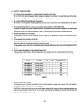
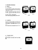
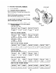

*RGX505, RGX505D
l
50Hz 22OV. 23OV, 240V
yzJG-Jq ml
l
50H.z 1 lOV, llOVI22OV. 12OVl24OV
l
60Hz 11OV. 12OV, llOVi22OV. 12OVi24OV
1 Wire color i BLUE 1
I
BLUE
] 0.14 52 1
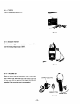
9-l-2 MEASURING INSULATION RESISTANCE
Refer to
8-4 MEASURING INSULATION RESISTANCE.
ROTOR
9-2 ROTOR ASSEMBLY
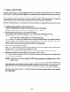
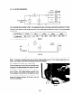
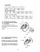
9-2-l WWDING RESISTANCE MEASURING
Check the resistance between the two slip rings with a test-
er. (See Fig. 9-2.)
The resistance is normal if it is anywhere from 5 ohms to
7.5 ohms.
TESTER
Fig. 9-2
9-2-2 MEASURING INSULATION RESISTANCE
Refer to
8-4 MEASURING INSULATION RESISTANCE.
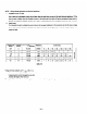
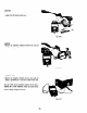
9-2-3 CLEANING SLIP RINGS
The slip ring surfaces must be uniformly bright. Slip rings
showing black spots, excessive wear, or uneven wear must
be repaired. A stained slip ring lowers generator efficiency
and output voltage. Polish the slip rings with fine sandpaper
while turning the rotor until rough spots disappear. Care
should be taken not to touch the rotor coils with the sand-
paper. (See Fig. 9-3.)
SANDPAPER
Fig. 9-3
- 37 -