RGX3000 RGX3800 RGX5100 RGX7100 RGX7800 3ZZ9990434 Original RGX3000 RGX3800 RGX5100 RGX7100 RGX7800
RGX7800 ce_GU6809 09.9.17 6:00 PM ページ001 (California Proposition 65) DANGER Using a generator indoors CAN KILL YOU IN MINUTES. Generator exhaust contains carbon monoxide. This is a poison you cannot see or smell. NEVER use inside a home or garage, EVEN IF doors and windows are open. Only use OUTSIDE and far away from windows, doors, and vents. WARNING : The engine exhaust from this product contains chemicals known to the State of California to cause cancer, birth defects or other reproductive harm.
RGX7800 ce_GU6809 09.9.17 6:00 PM ページ002 FEDERAL EMISSIONS COMPONENT DEFECT WARRANTY EMISSIONS COMPONENT DEFECT WARRANTY COVERAGE – This emission warranty is applicable in all States, except the state of California. Fuji Heavy Industries Ltd. and Robin America Inc.
RGX7800 ce_GU6809 09.9.17 6:00 PM ページ01 Thank you for purchasing a Robin generator. This manual covers operation and maintenance of the Robin generators. All information in this publication is based on the latest production information available at the time of approval for printing. Pay special attention to statements preceded by the following words: DANGER Indicates a possibility of death or serious injury if instructions are not followed.
RGX7800 ce_GU6809 09.9.17 6:00 PM ページ02 CONTENTS 1. SAFETY PRECAUTIONS ・・・・・・・・・・・・・・・・ 1 2. SPECIFICATIONS ・・・・・・・・・・・・・・・・・・・ 3 3. COMPONENTS ・・・・・・・・・・・・・・・・・・・・ 4 4. PRE-OPERATION CHECKS・・・・・・・・・・・・・・・ 7 5. OPERATING PROCEDURES ・・・・・・・・・・・・・・11 6. WATTAGE INFORMATION ・・・・・・・・・・・・・・・22 7. SPARK ARRESTER ・・・・・・・・・・・・・・・・・・24 8. MAINTENANCE SCHEDULE ・・・・・・・・・・・・・・25 9. "HOW-TO" MAINTENANCE・・・・・・・・・・・・・・・27 10. PREPARATION FOR STORAGE ・・・・・・・・・・・・・31 11. TROUBLESHOOTING ・・・・・・・・・・・・・・・・・32 12.
RGX7800 ce_GU6809 09.9.17 6:00 PM ページ1 1. SAFETY PRECAUTIONS ENGLISH Please make sure you review each precaution carefully. WARNING Do not operate the generator near gasoline or gaseous fuel because of the potential danger of explosion or fire. Do not fill the fuel tank with fuel while the engine is running. Do not smoke or use open flame near the fuel tank. Be careful not to spill fuel during refueling. If fuel is spilt, wipe it off and let dry before starting the engine.
RGX7800 ce_GU6809 09.9.17 6:00 PM ページ2 WARNING Do not operate in rain, in wet or damp conditions, or with wet hands. The operator may suffer severe electric shock if the generator is wet due to rain or snow. WARNING If wet, wipe and dry it well before starting. Do not pour water directly over the generator, nor wash it with water. WARNING Be extremely careful that all necessary electrical grounding procedures are followed during each and every use. Failure to do so can be fatal.
RGX7800 ce_GU6809 09.9.17 6:00 PM ページ3 MODEL RGX3000 RGX3800 RGX5100 RGX7100 RGX7800 Brush, self-exciting, 2-poles, single phase Type AVR type Voltage regulating system AC Output Generator Rated voltage-Frequency V-Hz Rated current A Rated output VA (W) 120-60 120/240-60 20 24.2 / 12.1 35 / 17.5 41.7 / 20.8 50 / 25 2400 2900 4200 5000 6000 Rated power factor 1.0 Safety device type Fuse-less circuit breaker DC Output Rated voltage V Rated current A 12 8.
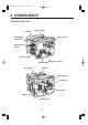
RGX7800 ce_GU6809 09.9.17 6:00 PM ページ4 3.
RGX7800 ce_GU6809 09.9.
RGX7800 ce_GU6809 09.9.
RGX7800 ce_GU6809 09.9.17 6:00 PM ページ7 4. PRE-OPERATION CHECKS Before checking or refilling oil, be sure generator is located on stable and level surface with engine stopped. ■ ■ ■ Remove oil filler cap and check the engine oil level. If oil level is below the lower level line, refill with suitable oil (see table) to upper level line. Do not screw in the oil filler cap when checking oil level. ENGLISH CHECK ENGINE OIL Oil filler cap (Oil gauge) Upper level Lower level Change oil if contaminated.
RGX7800 ce_GU6809 09.9.17 6:00 PM ページ8 CHECK ENGINE FUEL. WARNING Do not refuel while smoking or near open flame or other such potential fire hazards. Otherwise fire accident may occur. NOTE : THIS ENGINE IS CERTIFIED TO OPERATE ON AUTOMOTIVE UNLEADED GASOLINE. LEVEL Check fuel level at fuel level gauge. ■ If fuel level is low, refill with unleaded automotive gasoline. ■ Be sure to use the fuel filter screen on the fuel filter neck.
RGX7800 ce_GU6809 09.9.17 6:00 PM ページ9 ENGLISH CHECKING COMPONENT PARTS Check following items before starting engine: ■ Fuel leakage from fuel hose, etc. ■ Bolts and nuts for looseness. ■ Components for damage or breakage. ■ Generator not resting on or against any adjacent wiring. CHECK GENERATOR SURROUNDINGS WARNING Make sure you review each warning in order to prevent fire hazard. ■ Keep area clear of in flammables or other hazardous materials.
RGX7800 ce_GU6809 09.9.17 6:00 PM ページ10 WARNING Death, personal injury and/or property damage may occur unless instructions are followed carefully. ■ ■ ■ ■ ■ Use battery of recommended capacity. Turn the starter switch to the "STOP" position when mounting or dismounting battery. When mounting battery, connect the positive (+) cable first and then the negative (-) cable to the battery. Be careful not to short battery cables. When dismounting battery, disconnect negative (-) cable first.
RGX7800 ce_GU6809 09.9.17 6:00 PM ページ11 5. OPERATING PROCEDURES ENGLISH STARTING THE GENERATOR [CAUTION] Check the oil level before each operations as outlined by the article "CHECK ENGINE OIL" (a) Turn the Engine switch to the position "ON". ON OFF (b) Turn the AC circuit breaker to the position "OFF". ON OFF OFF (c) Open the fuel valve. CLOSE CLOSE OPEN (d) Set choke lever to close if the engine is cold.
RGX7800 ce_GU6809 09.9.17 6:00 PM ページ12 (e) [Recoil starter model] Pull the starter handle slowly until passing the compression point (resistance will be felt), then return the handle to its original position and pull briskly. ■ ■ ■ ly isk r ll b Pu If the engine fails to start after several attempts, repeat above procedures with choke lever returned to "OPEN" position. Do not fully pull out the rope.
RGX7800 ce_GU6809 09.9.17 6:00 PM ページ13 ( g) After the engine started, return the choke lever gradually to "OPEN" position. ENGLISH Choke lever CLOSE OPEN (h) Warm up the engine without a load for a few minutes.
RGX7800 ce_GU6809 09.9.17 6:00 PM ページ14 USING ELECTRIC POWER WARNING ■ ■ ■ Make sure that the appliance is switched OFF before connecting it to the generator. Do not move the generator while it is running. Be sure to ground the generator if the connected appliance is grounded. Failure to ground unit may lead to electrical shock. (1) AC APPLICATION (a) Make sure the pilot lamp is turned on. (b) Turn off the switch (es) of the electrical appliance (s) before connecting to the generator.
Style Ampere Receptacle AC plug Description up to 20A NEMA 5-20R NEMA 5-20P GFCI (Ground Fault Circuit Interrupter) Receptacle, duplex up to 30A NEMA L5-30R NEMA L5-30P Locking Receptacle (REC3) up to 30A NEMA L14-30R NEMA L14-30P Locking Receptacle (REC4) (REC1) TABLE 1 WARNING ■ ■ To take power out from the TWIST LOCK RECEPTACLE, insert the plug into the receptacle, and turn it clockwise to the lock position.
RGX7800 ce_GU6809 09.9.17 6:00 PM ページ16 (d) Turn the AC circuit breaker to the position "ON". ON (e) Turn on the switch of the appliance. ON OFF GFCI RECEPTACLE After starting the engine, check the GFCI for proper functioning by the following test procedure. ■ ■ ■ Push blue TEST button, The red RESET button will pop out exposing the word TRIP. Power is now off at the outlets protected by the GFCI, indicating that the device is functioning properly.
RGX7800 ce_GU6809 09.9.17 6:00 PM ページ17 ENGLISH FULL POWER SWITCH (Except RGX3000) Select the voltage using the FULL POWER SWITCH in accordance with the electrical appliance. Refer to TABLE 2. 120V 240V 120V [CAUTION] Change the FULL POWER SWITCH after turning the AC circuit breaker to "OFF". Switch position Lower Voltage Receptacle Higher Voltage Receptacle 120V Activated full rated output N.
RGX7800 ce_GU6809 09.9.17 6:00 PM ページ18 IDLE CONTROL SWITCH (Except RGX3000) IDLE CONTROL SWITCH automatically reduces engine speed when load is OFF, and automatically increases engine speed to rated r.p.m. when load is ON. IDLE CONTROL SWITCH provides fuel economy and low noise operation at noload running. (1) HOW TO USE IDLE CONTROL SWITCH ■ Start the engine with IDLE CONTROL SWITCH off. OFF ON NOTE : Warm up the engine without a load for a few minutes. ■ Turn IDLE CONTROL SWITCH on.
(2) DC APPLICATION (Only for charging 12 volt battery) DC receptacle (Only for charging 12 volt battery) BLACK CABLE RED CABLE + - For charging 12 voltage battery, 12V-8.3A (100W) of maximum AC power can be taken out from the DC receptacle by means of the exclusive DC cable. DC receptacle The exclusive DC cable is come with your generator set (included in the package).
RGX7800 ce_GU6809 09.9.17 6:00 PM ページ20 Battery Charging Procedures : 1) Stop engine. 2) Remove all connections from battery. 3) Insert the plug of exclusive DC cable into DC receptacle. 4) Connect positive (red) clip of DC cable to positive (+) terminal on battery, and then connect negative (black) clip of DC cable to negative (-) terminal on battery. 5) Take out all plugs at the battery electrolyte fluid filler ports. 6) Check the electrolyte fluid level, and refill the distilled water as necessary.
RGX7800 ce_GU6809 09.9.17 6:00 PM ページ21 ON ENGLISH STOPPING THE GENERATOR (a) Turn off the power switch of the electric equipment and unplug the cord from receptacle of the generator. OFF OFF (b) Turn the AC circuit breaker to the "OFF" position. ON (c) Allow the engine about 3 minutes to cool down at no-load before stopping. (d)[Recoil starter model] Turn the engine switch to the position "OFF". OFF STOP STOP [Electric starter model] Turn the key switch to the STOP position.
RGX7800 ce_GU6809 09.9.17 6:00 PM ページ22 6. WATTAGE INFORMATION Some appliances need a "surge" of energy when starting. This means that the amount of electrical power needed to start the appliance may exceed the amount needed to maintain its use. Electrical appliances and tools normally come with a label indicating voltage, cycles / Hz, amperage (amps) and electrical power needed to run the appliance or tool.
VOLTAGE DROP IN ELECTRIC EXTENSION CORDS When a long electric extension cord is used to connect an appliance or tool to the generator, a certain amount of voltage drop or loss occurs in the extension cord which reduces the effective voltage available for the appliance or tool. The chart below has been prepared to illustrate the approximate voltage loss when an extension cord of 300 feet (approx. 100 meters) is used to connect an appliance or tool to the generator. Allowable No.
RGX7800 ce_GU6809 09.9.17 6:00 PM ページ24 7. SPARK ARRESTER In a dry or wooded area, it is recommendable to use the product with a spark arrester. Some areas require the use of a spark arrester. Please check your local laws and regulations before operating your product. The spark arrester must be cleaned regularly to keep it functioning as designed.
RGX7800 ce_GU6809 09.9.17 6:00 PM ページ25 MAINTENANCE, REPLACEMENT, OR REPAIR OF THE EMISSION CONTROL DEVICES AND SYSTEMS MAY BE PERFORMED BY ANY NONROAD ENGINE REPAIR ESTABLISHMENT OR INDIVIDUAL.
RGX7800 ce_GU6809 09.9.
RGX7800 ce_GU6809 09.9.17 6:00 PM ページ27 9. "HOW-TO" MAINTENANCE ■ ENGLISH ENGINE OIL CHANGE Change engine oil every 100 hours. (For new engine, change oil after 20 hours.) (a) Drain oil by removing the drain plug and the oil filler cap while the engine is warm. Oil drain plug (b) Reinstall the drain plug and fill the engine with oil until it reaches the upper level on the oil filler cap. ■ Use fresh and high quality lubricating oil to the specified level as directed on page 7.
RGX7800 ce_GU6809 09.9.17 6:00 PM ページ28 CLEANING AND ADJUSTING SPARK PLUG (a) If the plug is contaminated with carbon, remove it using a plug cleaner or wire brush. (b) Adjust the electrode gap to 0.6 to 0.7 mm (0.024 to 0.028 in.). Gap 0.6 to 0.7 mm (0.024 to 0.028 in.) Spark plug : BR-6HS (NGK) CLEANING FUEL STRAINER Dirt and water in the fuel are removed by the fuel strainer. (a) Remove the strainer cup and throw away water and dirt. (b) Clean the screen and strainer cup with gasoline.
RGX7800 ce_GU6809 09.9.17 6:00 PM ページ29 ENGLISH CHECKING CARBON BRUSH Brush Maintenance Essentials (Effective Length) The brush is the area which touches the slip ring, and its surface must be kept smooth. If it is not smooth then carbon and other substances will adhere between the brush and slip ring. This must be buffed with sandpaper or the like because it is hazardous. The usable length of the brush is 5~11mm, so if the brush is 5mm long or less replace it with a new one.
RGX7800 ce_GU6809 09.9.17 6:00 PM ページ30 Brush Maintenance Essentials (Disassembly and Assembly) Disassembly 1. Remove the two flange bolts (M5 x 20), then remove the bracket cover. Brush 2. Remove the two flange bolts (M5 x 16), then remove the brush. Slip ring Assembly 1. While pressing the brush against the slip ring, secure it (1.5~2N・m) by tightening it with the two flange bolts (M5 x 16). When doing so, confirm that the brush is in the proper position relative to the slip ring. 2.
RGX7800 ce_GU6809 09.9.17 6:00 PM ページ31 The following procedures should be followed prior to storage of your generator for periods of 6 months or longer. ■ ■ ■ ■ ■ Drain fuel from fuel tank carefully by disconnecting the fuel line. Gasoline left in the fuel tank will eventually deteriorate making enginestarting difficult. Drain screw Remove the carburetor float chamber and also drain the carburetor. Change engine oil. Check for loose bolts and screws, tighten them if necessary.
RGX7800 ce_GU6809 09.9.17 6:00 PM ページ32 11. TROUBLESHOOTING When generator engine fails to start after several attempts, or if no electricity is available at the output socket, check the following chart. If your generator still fails to start or generate electricity, contact your nearest Robin dealer or service shop for further information or corrective procedures. When Engine Fails to Start : Check if choke lever is in its proper position. Set the choke lever to "CLOSE" Check if fuel valve is open.
Spark plug Y Blu Slip ring ROTOR GENERATOR AVR unit Brn Brn Blk Blu Blu Oil sensor switch Y Sub coil STATOR Ignition coil Y ENGINE Y − 33− Brn Brn Bridge diode AC winding 2 Grn/Y Y Y/R Y Blk AC winding 1 Org DC winding RGX3000 (60Hz-120V) Oil sensor unit Blk W Grn/Y Blu Org Gry R Grn/Y Blk W Grn/Y Blu R Hour meter DC circuit breaker Engine switch Blk CONTROL BOX W AC circuit breaker R PL : : : : Black Black/White Blue Light blue Wiring color code Blk Blk
Y Spark plug Blu Slip ring ROTOR AVR unit Brn Brn GENERATOR Blu Blu Y Sub coil STATOR Ignition coil Oil sensor switch Y Blk Y Y Blk Y Grn/Y Brn Brn Bridge diode AC winding 2 AC winding 1 Y/R Org Oil sensor unit Blk W Grn/Y Blu Blk W Grn/Y Blu Org Org R Gry W Gry R W Slowdown solenoid AC circuit breaker W Idle control switch W W W R DC circuit breaker AC circuit breaker R Blu PL 1 5 4 3 2 CONTROL BOX Idle control unit Pilot lamp ENGINE DC winding −
Y Blu Slip ring ROTOR GENERATOR Spark plug Battery AVR unit Brn Brn Y Sub coil Y Oil sensor unit Grn/Y Brn Bridge diode Brn AC winding 2 AC winding 1 STATOR Y Y/R Org Blk Blk Blk W Grn/Y Blu Blk W Grn/Y Blu Org R Org Electric starter Gry Magnetic switch W Gry R W Slowdown solenoid Blk Blu Blu Ignition coil Oil sensor switch Y R Blu Gry W AC circuit breaker Blu W W R Blu R DC circuit breaker AC circuit breaker 1 5 4 3 2 Blk R 11 8 5 Org 1 120/240
R Slip ring ROTOR GENERATOR Spark plug W Blk Sub coil STATOR AVR unit Grn Grn Y Blk Grn/Y Brn Bridge diode Brn AC winding 2 AC winding 1 Y/R Org Oil sensor unit R Blk Blk W Grn/Y Grn/Y W Blu Blu Org W Org W Gry Slowdown solenoid Gry R W Blu AC circuit breaker Idle control switch W DC circuit breaker PL 1 5 4 3 2 CONTROLBOX Hour meter ENGINE W W Idle control unit Pilot lamp Ignition coil Blu Blu W Blu 11 8 5 2 Blu Blk Blk/W Blu LBlu : : : : Bla
Battery R Slip ring ROTOR Blk Sub coil A VR unit Y Blk Blu Oil sensor unit Grn/Y Brn Brn Bridge diode AC winding 2 AC winding 1 Y/R Org STATOR Blu GENERATOR Spark plug W Blk W Grn/Y Blu Blk W Grn/Y Org Electric starter Org Magnetic switch W Gry Blu R Charge coil Gry R W Slowdown solenoid R Grn Grn Blu Blu Gry AC circuit breaker Blu W W DC circuit breaker PL 1 5 4 3 2 8 5 2 W Blu Blk Blk/W Blu LBlu : : : : Black Black/White Blue Light blue Wiring c
RGX7800 ce_GU6809 09.9.
RGX7800 cs_GU6809 09.9.