Recovery/ Recycling/ Recharging Unit Operating Manual Manual de Operación Manuel d’utilisation Model 17800B/17801B Recovery/Recycling/Recharging Unit for Multiple Refrigerants.....................................1 Modelo 17800B/17801B Unidad de recuperación/reciclado/recarga para múltiples refrigerantes.............................49 Modèl 17800B/17801B Poste de récupération/recyclage/ Recharge pour frigorigènes multiples..........
® Models 17800B / 17801B Recovery, Recycling, & Recharging Unit SAFETY DEFINITIONS: Follow all WARNING, CAUTION, and NOTE messages in this manual. These messages are defined as follows: WARNING means you may risk serious personal injury or death; CAUTION means you may risk personal injury, property damage, or unit damage; and NOTEs and OPERATING TIPS provide clarity and helpful information. These safety messages cover situations ROBINAIR is aware of.
Introduction ENGLISH This manual contains important safety procedures concerning the operation, use, and maintenance of this product. Failure to follow the instructions contained in this manual may result in serious injury. If you are unable to understand any of the contents of this manual, bring it to the attention of your supervisor. Do not operate this equipment unless you have read and understood the contents of this manual. TABLE OF CONTENTS Introduction..............................................
Introduction ENGLISH The 17800B/17801B is a complete A/C-R service center. It recovers, recycles, and recharges a wide range of refrigerants — from existing refrigerants to new substitutes and blends. With its multi-refrigerant capabilities, it is ideal for trucks, buses, and refrigerated trailers, as well as in-plant maintenance and other accessible installations. The built-in manifold means the entire service procedure can be done with just one hook-up.
Introduction GENERAL OPERATING GUIDELINES ENGLISH • The voltage at the unit must be ±10% of the unit’s rated voltage. Extension cords must be a minimum of 14 AWG and kept as short as possible. • To interrupt any procedure (other than clearing), press HOLD/CONT. Press HOLD/CONT again to resume operation. • System oil should be drained at the end of every recovery or recycling procedure, during the clearing process, or whenever oil is visible in the sight glass.
Setup Instructions ENGLISH Before you begin any procedure, familiarize yourself with the components of the unit. Lockout Door High Side Port Low Side Port Red Vapor Hose Blue Liquid Hose Yellow Air Purge Hose Tank Vapor Valve Tank Liquid Valve Air Purge Fitting 50 lb.
Setup Instructions ENGLISH Pressure / Temperature Chart Door Screw System Oil Drain Valve Door Screw INST0918 Diagram of Unit’s Components — Side View Liquid/Vapor Indicator Tank Pressure Gauge Tank Temperature Gauge System Oil Indicator Low Side Gauge High Side Gauge Air Purge Valve Oil-less Compressor Protector Display Main Power Switch High Side Valve Unit Circuit Breaker (17800B only) Low Side Valve Keypad INST0919 Diagram of Control Panel and Keypad Model 17800B / 17801B Recovery/Recycli
Setup Instructions ENGLISH Before starting the set up procedures, open the system oil drain valve and allow the unit to depressurize. 1. Plug the unit into a correct voltage outlet. WARNING: Avoid the use of an extension cord because the extension cord may overheat. However, if you must use an extension cord, use a No. 14 AWG minimum and keep the cord length to 25 feet (7.6 meters) or less. 2. Verify the oil drain valve on the side of the unit is in the CLOSED position. 3. Turn on the unit.
Setup Instructions ENGLISH 5. A new tank comes with a dry nitrogen charge of 5 to 10 psi to keep it clean and dry during shipment. Purge the nitrogen charge on the R-12 (gray and yellow) tank by opening the GAS (vapor) valve on the tank. Vent the pressure to the atmosphere; then close the valve. 6. Place the unit tank inside the ring on the scale platform on the back of the unit.
ENGLISH Setup Instructions The VacuMaster® vacuum pump is shipped without oil in the reservoir. Before starting the unit, fill the pump with oil. Two 16-ounce (472 milliliters) bottles of oil are included with your unit. 9. Remove the door access screws from the right side of the unit. Open the door. CAUTION: The pump must be running when adding oil. Do not overfill the pump. The approximate oil charge is 13 oz. (384 milliliters). 10. Remove the black plastic plug from the pump’s oil fill port.
Setup Instructions ENGLISH The 50 lb (23kg) unit tank must be filled with refrigerant before the unit is ready for use. TANK FILL 1. Connect the 96" blue low-side hose to the liquid valve fitting on the source tank. If using R-134a, you may need the 1/2" acme to low-side adapter included in the accessory kit. Note: Some tanks have slightly different valve configurations. Be sure to connect the blue hose to the LIQUID valve. This valve may be red on some tanks and blue on others. 2.
Operating Instructions RECOVERY PROCEDURES ENGLISH WARNING: Wear safety goggles when working with refrigerant. Use only authorized refillable refrigerant tanks. Disconnect hoses using extreme caution! All hoses may contain refrigerant under pressure. Read and follow all warnings at the beginning of this manual before operating the unit. Before beginning recovery, verify the unit is set up as described in the Setup Instructions. Also verify there is vacuum pump oil in the vacuum pump. 1.
Operating Instructions Hold CL-L ENGLISH The “CL-L” message shows on the display if there is pressure in the unit, and a self-clearing process of the components begins. You can press HOLD/CONT to bypass clearing if an accurate recovery amount is not required. Otherwise, the compressor will start and the “CL-L” message remains on the display. This process takes from 20 seconds to four minutes to complete. Once the clearing is complete, the unit automatically begins to recover refrigerant from the system.
ENGLISH Operating Instructions Lockout Door High Side Port Low Side Port Red Vapor Hose Blue Liquid Hose Air Purge Hose Tank Vapor Valve Tank Liquid Valve NOTE: Perform “RECOVERY PROCEDURES” before starting “CHANGING REFRIGERANT TYPES.” Air Purge Fitting 50 lb. (23 kg) Unit Tank INST0916 Scale Assembly Diagram of Unit’s Components — External View CAUTION: Before changing CHANGING REFRIGERANT TYPES refrigerant types, 1. Verify the red high-side and blue low-side hoses are disconnected from the.
Operating Instructions 4. If you need to change hoses for the next refrigerant type, go to Step 5. If you do not need to change hoses, press SHIFT/RESET and go to Step 6. door HOLD 6. Close the tank valves and disconnect the red, blue, and yellow hoses from the tank. Then remove the tank from the unit. 7. If you are using the same hoses for the next refrigerant type, go to Step 11. If you need to change the hoses, go to Step 8. 8. Disconnect all five (5) hoses from the lockout box fittings.
Operating Instructions A/C-R SYSTEM EVACUATION ENGLISH WARNING: Wear safety goggles when working with refrigerant. Use only authorized refillable refrigerant tanks. Disconnect hoses using extreme caution! All hoses may contain refrigerant under pressure. Read and follow all warnings at the beginning of this manual before operating the unit. PROGRAM I5.00 VACUUM MINUTES CPL Con 14 2. Press SHIFT/RESET to toggle the display to show “PROGRAM VACUUM MINUTES 15.00.
Operating Instructions RECYCLING PROCEDURES ENGLISH WARNING: Wear safety goggles when working with refrigerant. Use only authorized refillable refrigerant tanks. Disconnect hoses using extreme caution! All hoses may contain refrigerant under pressure. Read and follow all warnings at the beginning of this manual before operating the unit. 1. Verify both valves on the tank are open. 2. Press and hold SHIFT/RESET, then press “1” to start the recycling process.
Operating Instructions CHARGING PROCEDURES ENGLISH WARNING: Wear safety goggles when working with refrigerant. Use only authorized refillable refrigerant tanks. Disconnect hoses using extreme caution! All hoses may contain refrigerant under pressure. Read and follow all warnings at the beginning of this manual before operating the unit. HOLD Add The unit will display the message “CHECK REFRIGERANT” if there are less than six (6) pounds of refrigerant in the tank.
Operating Instructions If the unit beeps continuously, the transfer of refrigerant has stopped before the charging procedure was completed (see Correcting An Incomplete Transfer). ENGLISH 8. Close the high- and low-side valves on the control panel, and start the A/C-R system. Compare the gauge readings to the manufacturer’s specifications. 9. Turn off the A/C-R system, and disconnect the high-side hose from it. 10. Start the A/C-R system, and open both the high- and low-side valves.
Operating Instructions ENGLISH ADDING REFRIGERANT TO THE TANK CAUTION: R-134a systems have special fittings (per SAE specifications) to avoid cross-contamination with other refrigerant systems. Read and follow all warnings given at the beginning of this manual. CAUTION: When setting up for new types of refrigerant, a clearing process must be performed. NOTE: Purchase only tanks of R-134a refrigerant that have 1/2 inch (1.2cm) Acme threads. This is necessary to match the hose adapter. 1.
Operating Instructions This process takes about 45 minutes. You can interrupt it at any time by pressing HOLD/CONT once. Press HOLD/CONT again to resume operation, or press SHIFT/RESET to end the process. The transfer of new refrigerant is limited by weight to leave space (about 6 pounds of refrigerant) in the unit tank for recovery purposes. 9. Press RECOVER. The hose will be pulled into a partial vacuum and the unit will turn off automatically.
Operating Overview ENGLISH This overview is designed as a quick reference when using your unit. Read and follow all warnings in the operating manual. RECOVERY OVERVIEW 1. Connect the high- and low-side hoses to the A/C-R system. 2. Check the manifold gauges. There must be pressure to recover refrigerant. 3. Verify both the high- and low-side valves on the control panel are open. Also verify both valves on the tank are open. 4.
Operating Overview EVACUATION OVERVIEW 2. Press SHIFT/RESET to toggle the display to show “PROGRAM VACUUM MINUTES 15.00.” Fifteen minutes is the default time for evacuation. To change the time, press the appropriate keys to display the desired time. Then press ENTER. ENGLISH 1. Verify the high- and low-side hoses are connected to the A/C-R system, and that the high- and low-side valves are open. I5.
Operating Overview CHARGING OVERVIEW ENGLISH Follow the manufacturer’s recommendation for charging. You must replace any oil lost from the A/C-R system during recovery with new oil. Dispose of waste oil in an appropriate manner. PROGRAM 2.75 CHARGE LBS AUTOMATIC CHARGE LBS CPL VACUUM MINUTES *Enter the correct weight for your application. 22 4. Close the high- and low-side valves and start the A/C-R system. Compare the gauge readings to the manufacturer’s specifications. 5.
Maintenance Procedures CHANGING THE VACUUM PUMP OIL 1. Turn on the MAIN POWER switch. The display shows the selected refrigerant type. 2. Press SHIFT/RESET and the message “PROGRAM VACUUM MINUTES 15:00” displays. 3. Press VACUUM. The display shows the “OIL” message. 4. Remove the door access screws from the right side of the unit. Open the door. PROGRAM I5.
Maintenance Procedures ENGLISH CHANGING THE FILTER-DRIER Change the filter-drier whenever refrigerant has been recovered from a burn-out system or when the display shows the “CH-F” message (which means that the unit has recovered 200 pounds of refrigerant since the last change). To change the filter/ drier follow these steps: 1. Press and hold SHIFT/RESET and then press FILTER. The compressor will start and the display will show the messages “FIL” and “AUTOMATIC.” HOLD CH-F FIL LBS RECOVER 2.
Maintenance Procedures ENGLISH Filter-Drier FIL AUTOMATIC HOLD CPL O-ring Oil Return Manifold INST0922 Diagram of Filter-Drier Model 17800B/17801B Recovery/Recycling/Recharging Unit 25
Maintenance Procedures ENGLISH CONFIRMING THE SCALE CHECKLIST NOTE: Check the scale accuracy every three months. Blank Display or No Warnings Check the wire connections from the scale assembly to the circuit board for configuration and continuity. Verify the circuit board is receiving the correct voltage (refer to the decal on the back of the unit), and the two amp or 1/2 amp fuse is not blown. Use correctly grounded, active, electrical outlets only. Replace the circuit board or fuses as needed.
Maintenance Procedures ENGLISH 7. If the scale does not read the weight accurately, recalibrate the scale and UL circuit using the following instructions. If the scale does not respond to testing, verify the scale cable is plugged into the main circuit board. 8. Press SHIFT/RESET to exit this mode CALIBRATING THE SCALE NOTE: The scale assembly and UL circuit MUST be calibrated when installing a replacement scale assembly or circuit board.
Maintenance Procedures ENGLISH 12. To check scale accuracy, follow the Correct Weight Verification procedure. WARNING Unplug the unit before beginning service work. Incorrect use or connections can cause electrical shock. Only qualified personnel should perform service work. If scale assembly and UL circuit are not calibrated, scale can overfill the tank, causing possible explosion and/or vehicle overcharge. UL CIRCUIT CALIBRATION NOTE: Always calibrate the scale first.
Maintenance Procedures ENGLISH NOTE: Turning the P1 POT clockwise increases the weight capacity of the scale. Turning the P1-POT counterclockwise decreases the weight capacity of the scale. 8. Lift the weight from the scale and “HOLD” should appear. NOTE: The display should read “HOLD” for 75 lbs. ONLY, not for anything more or less. RL20 P1-POT HI-PRESSURE 2 AMP FUSE 2 AMP RL19 F2 R14 R8 1/2 AMP 9. If the UL circuit won’t calibrate, replace the main circuit board.
Maintenance Procedures ENGLISH CHECKING FOR LEAKS NOTE: Inspect the unit periodically for leaks. The manufacturer does not reimburse for lost refrigerant. Every three months, or as often as required by local or state laws, check the unit for leaks. As with any mechanical equipment, general use, moving the unit, and vibration can cause fittings to loosen. 1. Turn off the MAIN POWER switch, and disconnect the power cord from the outlet. 2. Remove the door access screws from the right side of the unit.
Operating Guidelines USING THE CONTROL PANEL ENGLISH MAIN POWER Switch — Supplies electrical power to the control panel. Digital Display — Shows the time programmed for vacuum, and the weight of refrigerant programmed for recharging. Detailed instructions for programming the digital display follow this section. Air Purge Indicator — Shows when non-condensables need to be purged from the tank. LIQUID/VAPOR Indicator — Shows if liquid or vapor refrigerant is being recovered.
Operating Guidelines KEYPAD FUNCTIONS ENGLISH In addition to the number keys, the keypad contains special keys that accomplish specific operating functions. • RECYCLE — Activates the recycling sequence when pressed at the same time as the SHIFT/RESET key. • RECOVER — Activates the recovery sequence. Diagram of Keypad • SHIFT/RESET — Accesses the “PROGRAM” mode and moves from one program function to the next.
Operating Guidelines Segment A — Indicates in which mode the unit is operating: ENGLISH PROGRAM — The unit is in the programming mode, which allows you to program vacuum time and refrigerant weight or review the existing program. HOLD — This mode is used to change a refrigerant tank or to interrupt the vacuum/charging/recovery cycles. AUTOMATIC — Indicates the unit is running in a given cycle and will automatically stop when the cycle is complete.
Operating Guidelines RECOVER ENGLISH • With AUTOMATIC, indicates the unit is recovering refrigerant from the A/C-R system and shows the amount of refrigerant recovered in pounds or kilograms, depending on the measurement mode selected. OIL (OUNCES) or OIL (GRAMS) • Lights up as a reminder to drain the oil separator after each job. Segment C — Shows a number or a coded error message on the digital display that indicates the unit’s operating status or any specific problems.
Operating Guidelines USING THE DIAGNOSTIC MODE Some diagnostic functions exit the diagnostic mode when completed, so to continue with more diagnostic functions you must re-enter the diagnostic mode. ENGLISH The diagnostic mode allows you to run individual components or retrieve stored information. To access the diagnostic mode, press and hold SHIFT/RESET and then press ENTER. The display will show the message “FUNC.” To exit the diagnostic mode, press SHIFT/RESET again.
Operating Guidelines To Test Full Display: ENGLISH VACUUM RECYCLE MINUTES CHARGE KG LB RECOVER OIL(GRAMS) CHECK REFRIGERANT OIL(OUNCES) PROGRAM HOLD AUTOMATIC 8.8.8.8 1. Press “5” to see the complete LCD display, which displays only momentarily before returning to Program mode. 2. Press any key to exit. Example of Full Display Test To Access Scale Function: 1. Press “6” to zero-out the display (regardless of what is on the scale platform).
Operating Guidelines USING DISPLAY CODES ENGLISH 134A ��������������������R-134a; indicates R-134a automotive refrigerant requiring 1/2" Acme fittings. Add ����������������������Add refrigerant to the tank before starting charging procedures. CAL ��������������������The scale is out of calibration; see Calibrating the Scale. Check ����������������Tank has six (6) pounds or less of refrigerant; Refrigerant charging will not activate.
Operating Guidelines ENGLISH OIL ����������������������Change vacuum pump oil; it has been 10 hours since the last oil change. R12 ����������������������R-12; indicates R-12 or other refrigerant type requiring 1/4" flare fittings. SCAL ������������������Scale problem; the scale is broken or disconnected, or the tank has exceeded 75 pounds gross weight. U-HI ��������������������High pressure to vacuum pump; prevents blowing refrigerant through the vacuum pump.
Replacement Parts Description ENGLISH Following is a list of replacement parts and accessories you may need to service or maintain your unit. Tanks, filter-drier, and vacuum pump oil should be purchased through your regular Robinair distributor. Part No. 50 lb. (23 kg) tank,1/4 in. flare fittings----------------------------------------- 17506 50 lb. (23 kg) tank,1/2 in.
ENGLISH Flow Diagram Component List SW1 SW2 SW3 SW4 S1 S2 S3 S4 S5 S6 S7 S8 S9 S10 S11 S12 S13 S14 C1 C2 C3 C4 C5 C6 B1 B2 B3 SWITCHES Vacuum Protection (B2) Vacuum (stand alone) Oil Drain (stand alone) HPCO (B3) SOLENOIDS Recover (B2) Liq/Vap (B2) Self/CLR (B3) Chk Vlv (B3) Oil Return (B3) R12 Vapor (B1) 134a Vapor (B1) R12 Liquid (B1) 134a Liquid (B1) Charge (B2) Recycle (stand alone) Vacuum (B2) Clearing/Vacuum (B3) Free Air (stand alone) CHECK VALVES Charge (B2) Vapor IN (B2) Liquid IN (B2) R12 Vapor
Model 17800B/17801B Recovery/Recycling/Recharging Unit yellow yellow blue brown blue brown blue brown black yellow yellow red red white white orange orange white white violet violet black black blue blue orange orange white white blue blue yellow yellow red red Liq/Vap Light R134a Vap Sol 7 R134a Liq Sol 9 R12 Vapor Sol 6 R12 Liquid Sol 8 Clear Vac Sol 13 Oil Ret Sol 5 Self/CLR Sol 3 Chk Vlv Sol 4 Vacuu
Recover Sol 1 Liq/Vap Sol 2 Recycle Sol 11 Charge Sol 10 Vacuum Sol 12 Self/CLR Sol 3 Oil Ret Sol 5 R12 Liquid Sol 8 R12 Vapor Sol 6 R134a Liq Sol 9 R134a Vap Sol 7 black black white white orange orange red red yellow yellow brown brown blue green/yellow brown brown blue red black Door Switch Vac Prot SW 1 Vacuum SW 2 Oil Drain SW 3 Float Switch High Press SW 4 brown blue Vacuum Pump L M Compressor Start Relay Thomas Compressor Oil Full Light S Heater Band Start C
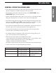
Troubleshooting RECOVERY OPERATION Problem: Solution: Main power switch is off. Turn on switch. Problem: Solution: Power cord is not plugged in, or there is no power at plug. Check circuit for power. Problem: Solution: “FULL” message shows on digital display. Change tanks (see Installing a Tank and Pulling A Vacuum). Problem: Solution: “HI-P” message shows on digital display.
Troubleshooting ENGLISH Runs but will not shut off Problem: Solution: Oil drain valve is open. Close the oil drain valve. Problem: Solution: There is a leak in the A/C-R system. Locate and repair all system leaks. Problem: Solution: Hoses are not connected to the vehicle. Check hose connections. Problem: Solution: Oil return solenoid is open. Replace the oil return solenoid.
Troubleshooting RECHARGING OPERATION Problem: Solution: Power cord is not plugged in, or there is no power at plug. Check circuit for power. Problem: Solution: The “CHECK REFRIGERANT” message is displayed. There are less than 6 pounds of refrigerant in the tank; add refrigerant to the tank. ENGLISH No power when MAIN POWER switch is on — no display showing Audible tone sounds during refrigerant transfer Problem: Solution: Transfer stopped or too slow.
Troubleshooting EVACUATION OPERATION ENGLISH Vacuum pump will not start Problem: Solution: Power cord is not plugged in, or there is no power at plug. Check circuit for power. Problem: Solution: The pressure in the A/C-R system is too high. Recover the remaining A/C-R system charge. Problem: Solution: “U-HI” message on digital display. Recover all refrigerant before pulling a vacuum. Problem: Solution: Vacuum time not entered. Program the required time for vacuum.
Limited Warranty Robinair Limited Warranty Statement Rev. November 1, 2005 ENGLISH This product is warranted to be free from defects in workmanship, materials, and components for a period of one year from date of purchase. All parts and labor required to repair defective products covered under the warranty will be at no charge. The following restrictions apply: 1. The limited warranty applies to the original purchaser only. 2.
Notes A/C-R System Evacuation . . . . . . . . . . . . . . . . . 14 Adding Refrigerant to the Tank . . . . . . . . . . . . . 18 ENGLISH Calibrating the Scale . . . . . . . . . . . . . . . . . . . . . 27 Circuit Calibration, UL . . . . . . . . . . . . . . . . . . . . 28 Changing Refrigerant Types . . . . . . . . . . . . . . . 12 Changing the Filter-Drier . . . . . . . . . . . . . . . . . .
Conversion Table Tabla de conversión Table de Conversion OZ. onzas 0.5 1.0 1.5 2.0 2.5 3.0 3.5 4.0 4.5 5.0 5.5 6.0 6.5 7.0 7.5 8.0 8.5 9.0 9.5 10.0 10.5 11.0 11.5 12.0 12.5 13.0 13.5 14.0 14.5 15.0 15.5 16.0 LBS. libras 0.03 0.06 0.09 0.13 0.16 0.19 0.22 0.25 0.28 0.31 0.34 0.38 0.41 0.44 0.47 0.50 0.53 0.56 0.59 0.63 0.66 0.69 0.72 0.75 0.78 0.81 0.84 0.88 0.91 0.94 0.97 1 lb. Visit our web site at www.robinair.com or call our toll-free Technical Support Line at 800-822-5561 in the continental U.S.