
Owner manual

© Bosch Automotive Service Solutions LLC
40
ENGLISH
INST0923
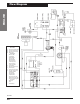
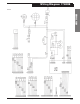
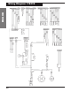
Flow Diagram
Component List
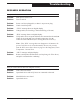
SWITCHES
SW1 Vacuum Protection (B2)
SW2 Vacuum (stand alone)
SW3 Oil Drain (stand alone)
SW4 HPCO (B3)
SOLENOIDS
S1 Recover (B2)
S2 Liq/Vap (B2)
S3 Self/CLR (B3)
S4 Chk Vlv (B3)
S5 Oil Return (B3)
S6 R12 Vapor (B1)
S7 134a Vapor (B1)
S8 R12 Liquid (B1)
S9 134a Liquid (B1)
S10 Charge (B2)
S11 Recycle (stand alone)
S12 Vacuum (B2)
S13 Clearing/Vacuum (B3)
S14 Free Air (stand alone)
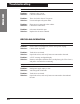
CHECK VALVES
C1 Charge (B2)
C2 Vapor IN (B2)
C3 Liquid IN (B2)
C4 R12 Vapor OUT (B1)
C5 R134a Vapor OUT (B1)
C6 High-side Clearing (B1)
BLOCKS
B1 Bulkhead
B2 Inlet
B3 Filter/Oil Sep.