○ ○ ○ ○ ○ ○ ○ ○ ○ ○ ○ ○ ○ ○ ○ ○ ○ ○ ○ ○ ○ ○ ○ ○ ○ ○ ○ ○ ○ ○ ○ ○ ○ ○ ○ ○ ○ ○ ○ ○ ○ ○ ○ ○ ○ ○ ○ ○ ○ ○ ○ ○ ○ ○ ○ ○ ○ ○ ○ ○ ○ ○ ○ ○ ○ ○ ○ ○ ○ ○ ○ ○ ○ ○ ○ ○ ○ Operating Manual Model 342000 Refrigerant Service Solution
Refrigerant: R-134a Series: 342000 Air Conditioning and Refrigerant Service Solution SAFETY DEFINITIONS: Follow all WARNING, CAUTION, IMPORTANT, and NOTE messages in this manual. These messages are defined as follows: WARNING means you may risk serious personal injury or death; CAUTION means you may risk personal injury, property damage, or serious unit damage; IMPORTANT means you may risk unit damage; and NOTEs provide clarity and helpful tips. These safety messages cover situations ROBINAIR is aware of.
Table of Contents Introduction .............................................................................................. 2 Glossary of Terms ................................................................................ 2 General Operating Guidelines .............................................................. 3 Component Location and Identification ................................................ 4 342000 Overview ....................................................................................
Introduction This manual contains important safety procedures concerning the operation, use and maintenance of this product. Failure to follow the instructions contained in this manual may result in serious injury. If you are unable to understand any of the contents of this manual, please bring it to the attention of your supervisor. Do not operate this equipment unless you have read and understand the contents of this manual. The 342000 is a complete air conditioning service center for R-134a.
Introduction GENERAL OPERATING GUIDELINES Use the following guidelines when operating the 342000: 1. The voltage at the unit must be ±10% of the unit’s rated voltage. Errors will be displayed on the screen. Extension cords must be a minimum of 14 AWG and kept as short as possible.
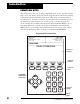
Introduction COMPONENT LOCATION AND IDENTIFICATION 342000 CONTROL PANEL Low Side Gauge High Side Gauge Display Function Keys Numeric Keys Refrigerant Identifier Filter Main Power Switch Printer Arrow Keys Display Contrast Keys INST 0684 4 © 1999 Robinair, SPX Corporation
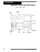
Introduction COMPONENT LOCATION AND IDENTIFICATION 342000 FRONT VIEW Control Panel “Cycle Complete” Red Indicator Light Convenient Built-in Handle and Hose Storage Shelf for tools and accessories Oil Injection Bottle Filter-Drier Access Oil Drain Bottle Polypropylene Cabinet for durability and light weight INST 0685 Large Wheels for mobility across air lines, power cords, grates Locking Casters 342000 SIDE VIEW Convenient Handle for moving unit Vacuum Pump Oil Level Sight Glass and Oil Fill Port O
Introduction 342000 OVERVIEW Before you begin any procedure, familiarize yourself with its functions, the components of the unit (see diagrams in this section) and its operation. 1. POWER UP—When the power is turned ON, the unit performs selfdiagnostics. When tests are complete, the display shows SELECT OPERATION. Use the function keys (F-1 to F-5) to select the desired operating mode. 2.
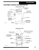
Introduction COMPONENT LOCATION AND IDENTIFICATION 342000 Temperature and Velocity Probes (located on back panel) Circuit Breakers Blue Temp Probe Red Temp Probe Anemometer RS232 Outlet INST0687 A/C System Close-Up of Oil Drain Connection (located on side panel near tank) Oil Drain Bottle simply snaps into place (Be sure the drain tube is inside the bottle) INST0688 342000 Refrigerant Service Solution 7
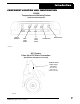
Introduction FUNCTION KEYS The function keys (F-1 to F-5) change depending on the service operation and the unit’s status. The display shows five labels along the bottom with arrows pointing to the function keys below. Each label shows what action a particular function key will activate. To make a selection, press the function key immediately below the label/arrow. This display is not a touch screen—you must press the key. As an example, the last label in the illustration shows SCROLL MENU.
Introduction Set NUMBER KEYS Use these keys to change the evacuation time, vacuum level, or recharge weight if you want an amount different than the default one shown on the display. These keys are also used to enter other numeric values, such as your area’s elevation above sea level. UP/DOWN AND LEFT/RIGHT ARROW KEYS Pressing the UP/DOWN and RIGHT/LEFT keys moves the cursor on the screen in that direction (Up, Down, Right, or Left).
Initial Set-Up INITIAL SET-UP INSTRUCTIONS CAUTION! It is extremely important to follow these instructions! DO NOT attach any hoses or accessories until prompted by the unit. Improper set-up will result in unit failure! Use the following steps for initially setting up the 34200: 1. Attach the power cord to a 115V 60 Hz, 15 amp grounded outlet. Do not use extension cords. The unit display gives directions and explanations based on current vehicle/ service status.
Initial Set-Up 7. Attach the red (front) 15-foot temperature probe and blue (rear) 30-foot temperature probes and optional airflow sensor to the appropriately labeled connections at the upper rear. 8. The display will prompt you to add oil: ADD 5.0 OUNCES OF NEW OIL TO VACUUM PUMP PRESS START TO CONTINUE Add 5 ounces of oil, and press START. The vacuum pump will start, and the display will show: FILL WITH NEW OIL TO CENTER OF SIGHT GLASS (APPROX. 13.
Set-Up Instructions POWER UP After the initial setup is complete, the 342000 will be ready to be powered up. Use the following steps to power up the 342000: 1. Turn the Main Power Switch ON. 2. The display shows MAIN MENU and SELECT OPERATION when the unit is ready for operation. VEHICLES WITH CONTAMINATED SYSTEMS Before every recovery, the 342000 automatically samples the refrigerant in the vehicle system. The operator may not bypass this procedure.
Set-Up Instructions TESTING SOURCE TANKS (continued) To sample a source tank, follow these instructions: 1. Recover any refrigerant left in the hoses by pressing the RECOVER key. 2. Attach a 1/2" acme x low side adapter to the source tank. Use the vapor valve on the refillable tanks. 3. Attach the blue low side service hose to the adapter and open the coupler. 4. Open the source tank valve. 5. Turn ON the 342000. 6. Press the SNAPSHOT key. 7. Press the START key. 8.
Operating Instructions DIAGNOSING SYSTEM OPERATION USING SNAPSHOT MODE WARNING Always wear eye protection and protective clothing when working with refrigerants. Observe all warnings at the beginning of this manual. Be sure the vehicle is in PARK before turning on the engine. Provide adequate ventilation or pipe exhaust to outside. Vehicle exhaust fumes can cause injury or death.
Operating Instructions 3. Press the START key. 4. After identifying the vehicle refrigerant, the 342000 displays and updates minimum and maximum values described above. Pressing the RESET MIN/MAX key resets and begins tracking new Minimum and Maximum values. You can press the PRINT key at any time to capture and print the screen information.
Operating Instructions RECOVERING REFRIGERANT IMPORTANT: If you operate the engine during recovery, see warnings at the front of this manual and take extreme care to avoid moving parts. Recovery speed and accuracy is highly dependent on underhood temperature and air flow across components. Cold refrigerant can pool in the accumulator, evaporator or condenser and will continue to increase system pressures even after the recovery process has ended.
Operating Instructions • Wait for the 342000 to automatically restart and pull any additional ! ! refrigerant which has vaporized in the system (this occurs after five minutes if a positive pressure is detected). Additional recovered refrigerant is added to the amount shown on the screen. NOTE: If you have entered the RECOVERY mode through the SNAPSHOT mode, the unit will automatically return to SNAPSHOT when you exit RECOVERY and will give you an updated printout.
Operating Instructions NOTE: Depending on your altitude, you may not be able to achieve 28" Hg. It is important that the altitude setting in the Set-Up Menu is correct for your location. The 342000 uses this information to calculate and provide an equivalent set point for your altitude. For instance, at 7000 feet, the 342000 pulls to 21" Hg before completing evacuation. REPLENISHING A/C SYSTEM OIL WARNING! When running the engine, be sure the vehicle is in PARK and always provide adequate ventilation.
Operating Instructions NOTE: Oil is injected through the High Side (Red) Service Hose and the High Side Hose must be connected to the A/C system with the coupler valve open. NOTE: In order to draw oil into the A/C system, the system must be under vacuum (see page 17). 9. Press and hold the INJECT OIL key until the oil level reaches the O-ring. NOTE: Refrigerant must be charged through the high side into the A/C system after oil is injected to flush the oil from the hoses into the A/C system.
Operating Instructions 6. Upon pressing the START key, the 342000 begins to charge the A/C system. IMPORTANT: If the coupler valves on the high or low side are left open, the system will pull the refrigerant back out of the vehicle. IMPORTANT: Do not disturb or bump the 342000 during charge as any jarring movement can affect the charge accuracy.
Operating Instructions FLUSHING PROCESS The 342000 provides a method of removing oil by forcing liquid refrigerant through the A/C system or components of the A/C system. A special flushing adapter to access the system at the compressor block is available as an accessory. After flushing, the refrigerant is recovered by the 342000 and is filtered by the recycling circuit, returning it to SAE purity levels. A/C system configurations vary and may require adapting and flushing of individual components.
Operating Instructions 3. Press the NEXT key. If the refrigerant has not been recovered, the 342000 will now identify and recover. It then prompts you to make proper system connections (as outlined above) prior to evacuation or pulling a vacuum. IMPORTANT! Remember to replace system oil. Flushing removes all oil from the system. Follow instructions packed with the oil injector. 4. Press the VACUUM key. Choose the default or program the evacuation time, then press the START key.
Operating Instructions HELP SCREENS The following Help Screens appear on the 342000 for your convenience: VACUUM • Connect service hoses to vehicle and open coupler valves. • The system must have less than 25 psi of pressure for correct operation of the vacuum pump. • If greater than 25 psi, you must recover the refrigerant before proceeding. OIL FLUSH • Recover any refrigerant in the vehicle. • Remove and bypass the Orifice Tube or TXV. • Install compressor bypass block and filter kit.
Operating Instructions RECOVER • Verify that the service hoses are connected and the coupler valves are open. • The system must have at least 25 psi of pressure for correct operation of the refrigerant ID. SET-UP MENU (Use the UP/DOWN arrows to highlight selections) • Language - Press TOGGLE SELECTION to select English, Spanish, or French. - Press the MAIN key to exit. • Select Units (Selects the units of measure in English or Metric) - Press TOGGLE SELECTION. - Press the MAIN key to exit.
Maintenance CHANGING THE FILTER-DRIER The filter-drier is specially blended to remove maximum moisture, acid and other contaminants. It will recycle about 300 pounds (136.36 kgs) of refrigerant before a replacement is needed. The unit keeps track of jobs and total recycled refrigerant, and signals when it’s time to change the filter-drier. If the CHANGE FILTER message comes on during a job, it’s best to complete that job before changing the filter-drier.
Maintenance CHANGING THE FILTER-DRIER (continued) 4. When the clearing is complete, follow the on-screen prompts. 5. Turn the unit OFF and disconnect the power cord from the power outlet. WARNING Always disconnect the unit from the power source before making any repairs or replacements to components. Risk of electrical shock! 6. Open the unit’s front panel, remove the old filter-drier and replace it with a new one. Hand-tighten the new filter. Dispose of the used filter-drier properly. 7.
Maintenance ELECTRICAL PROTECTION The 342000 monitors voltage and disables circuitry if the voltage drops below 103.5 volts or increases above 135 volts. It also detects incorrectly wired connections and warns of the potential hazard. Additionally, the 342000 is protected by circuit breakers located on the back panel (see page 7). If the circuit breaker trips, all power to the unit is lost. Press the circuit breaker button to reset.
Maintenance OIL TIME WARNING If the vacuum pump has accumulated 600 minutes of operation without an oil change, the following message will appear when the user enters vacuum mode: CHANGE THE VACUUM OIL AS SOON AS POSSIBLE! SEE THE MANUAL FOR INSTRUCTIONS Press START to continue with the vacuum procedure. OIL CHANGE MENU/PROCESS Under the setup menu, one of the choices is CHANGE VACUUM OIL. When entered, the display shows: REMAINING VACUUM TIME: XXX.X MINUTES (xxx.x is the current remaining time. 501.
Maintenance REPLACING THE IDENTIFIER FILTER CAUTION! Visually inspect the identifier filter every day. If it begins to turn red, replace it immediately! You risk damaging the identifier if the filter isn’t replaced. The built-in refrigerant identifier has an inlet filter to protect the sensor. Periodically, this becomes clogged with contaminants and must be replaced. REPLACE THIS FILTER IMMEDIATELY! 1. The filter is located on the top of the unit’s control panel. Unplug it and remove it from the unit. 2.
Replacement Parts Description 30 Part Number Anemometer 19698 Filter Drier (spin-on) 34724 Hose, Red (96") 63096 Hose, Blue (96") 62096 Identifier Filter 16912 Oil Bottle 17756 Printer Paper 34215 Service Coupler (red) 18191 Service Coupler (blue) 18190 Temp. Probe, 15' 17915 Temp.
Notes 342000 Refrigerant Service Solution 31
Notes 32 © 1999 Robinair, SPX Corporation
Limited Warranty This product is warranted to be free from defects in workmanship, materials, and components for a period of one year from date of purchase. All parts and labor required to repair defective products covered under the warranty will be at no charge. The following restrictions apply: 1. The limited warranty applies to the original purchaser only. 2. The warranty applies to the product in normal usage situations only, as described in the Operating Manual.
CONVERSION TABLE OZ. LBS. 0.5 1.0 1.5 2.0 2.5 3.0 3.5 4.0 4.5 5.0 5.5 6.0 6.5 7.0 7.5 8.0 8.5 9.0 9.5 10.0 10.5 11.0 11.5 12.0 12.5 13.0 13.5 14.0 14.5 15.0 15.5 16.0 0.03 0.06 0.09 0.13 0.16 0.19 0.22 0.25 0.28 0.31 0.34 0.38 0.41 0.44 0.47 0.50 0.53 0.56 0.59 0.63 0.69 0.69 0.72 0.75 0.78 0.81 0.84 0.88 0.91 0.94 0.97 1 lb. Visit our web site at % www.robinair.com or call our toll-free Technical Support Line at 800-822-5561 in the continental U.S.