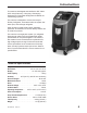
Original Instructions Instrucciones originales Instructions d’origine Model AC1234-6 Recover, Recycle, Recharge Machine for R1234yf A/C Systems
Description: Recover, recycle, and recharge machine for use with R1234yf equipped air conditioning systems. PRODUCT INFORMATION Record the serial number and year of manufacture of this unit for future reference. Refer to the product identification label on the unit for information.
Table of Contents Safety Precautions . . . . . . . . . . . . . . . . . . . . . . . . . . . . . . . . . . . . . . . . . . . 2 Introduction Technical Specifications . . . . . . . . . . . . . . . . . . . . . . . . . . . . . . . . . . . . . 5 Features of the AC1234-6 . . . . . . . . . . . . . . . . . . . . . . . . . . . . . . . . . . . . 6 Control Panel Functions . . . . . . . . . .
Safety Precautions Explanation of Safety Signal Words Used in this Manual The safety signal word designates the degree, or level, of hazard seriousness. DANGER: Indicates an imminently hazardous situation which, if not avoided, will result in death or serious injury. WARNING: Indicates a potentially hazardous situation which, if not avoided, could result in death or serious injury. CAUTION: Indicates a potentially hazardous situation which, if not avoided, may result in minor or moderate injury.
Safety Precautions WARNING : To prevent personal injury, ALLOW ONLY QUALIFIED PERSONNEL TO OPERATE THE MACHINE. Before operating the machine, read and follow the instructions and warnings in this manual. The operator must be familiar with air conditioning and refrigeration systems, refrigerants, and the dangers of pressurized components. If the operator cannot read this manual, operating instructions and safety precautions must be read and discussed in the operator’s native language.
Safety Precautions CAUTION : To prevent equipment damage, TO PREVENT CROSS-CONTAMINATION, USE THIS MACHINE WITH R1234YF REFRIGERANT ONLY. The machine is equipped with special connectors to recover, recycle, and recharge only R1234yf refrigerant. Do not attempt to adapt the machine for another refrigerant. Do not mix refrigerant types through a system or in the same container; mixing of refrigerants will cause severe damage to the machine and the vehicle air conditioning system.
Introduction This machine is designed and certified to SAE J2843 HFO-1234yf Recovery / Recycling / Recharging Equipment for Flammable Refrigerants for Mobile AirConditioning Systems. The machine is designed to recover and recycle R1234yf refrigerant, evacuate air after the system has been open, and recharge refrigerant. Other functions include system flush, diagnostic pressures, and retention of service data by vehicle VIN for recall and printout. The machine is a single-pass system (i.e.
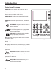
Introduction Features of the AC1234-6 4 OK 9 HELP MENU STOP ESC DATABASE 3 5 2 7 8 1 6 11 9 10 13 12 6
Introduction Features of the AC1234-6 continued Item No. AC1234-6 Description 1 Oil Drain Bottle 2 Printer 3 Low-side (blue) and High-side (red) Manifold Gauges 4 Graphic Display and Keypad 5 Power ON / OFF Switch 6 Audio, Ethernet, USB, Mini-USB, and SD Card Connections 7 Vacuum Pump Oil Sight Glass 8 Vacuum Pump Oil Drain Fitting 9 Wheel Lock 10 Visual Alert 11 Vacuum Pump Oil Fill Cap and Port 12 Contaminant Recovery Port 13 Service Hose Storage Ports Rev.
Introduction Control Panel Functions ARROW UP moves selection of a menu item to the previous item; turns up audio volume. ARROW DOWN moves selection of a menu item to the following item; turns down audio volume. ARROW RIGHT scrolls to next screen; fast forwards the video. ARROW LEFT scrolls to previous screen; rewinds the video. AUTOMATIC activates a menu to set up an automatic recovery / vacuum / leak test / charge sequence.
Introduction Setup Menu Functions Access the following functions by pressing the Menu key and selecting Setup. Air Purge Info Displays internal storage vessel (ISV) pressure and temperature. Use to check ISV for excessive pressure. Backlight Adjusts the contrast on the display screen. Beeper Setting Turns the audio “beep” OFF and ON. Calibration Check Use to verify internal scale calibration. Refer to Calibration Check in the Maintenance section.
Setup Unpack the Accessory Kit Unpack the accessory kit from the box, and remove the plastic packaging. Accessory Kit Calibration Weight 533 g Tank Fill Hose Adapter Cap and Filler Tube Vacuum Pump Oil 16 oz. Oil Drain Bottle Pouch containing a warranty card to be filled out and mailed, MSDSs, EPA information, MACS information, and a service center list. Install Oil Drain Bottle 1. Hold the oil drain bottle straight and insert the connector into the hole behind the shroud until it snaps into place.
Setup Power Up the Machine 1. Unwind the power cord from the handle, and plug it into a correct voltage, grounded outlet. 2. Position the machine so the plug and the main power switch are of easy access for the operator. Verify the fan vents on the rear of the machine are not obstructed. 3. Lock the front wheels. 4. Turn ON the main power switch. CAUTION: The machine is programmed to run the setup procedure as outlined here.
Setup Language Selection The operator selects the language for the screen prompt displays. English is the default language. 1. Use the UP or DOWN arrow key to toggle through the available languages. 2. Press OK to set the selected language. 3. The license agreement is displayed for your approval, after which the machine continues with SETUP mode. Unit of Measure The operator sets the display for units of measure. Metric is the default. 1.
Setup Tank Fill Adjustment The operator may either accept the machine’s pre-set default weight of 4.5 kg (10 lbs.) of refrigerant stored in the ISV, or change to a lesser amount to accommodate the application. The maximum amount allowed for new refrigerant is 6.8 kg, which leaves room for additional recovery. 1. The machine displays 4.5 KG Press OK to accept the default amount, or use the keypad to enter an amount and press OK.
Setup Garage Data First Fill Field This machine has the capability to print out recovery, vacuum, charge, and flush information for each vehicle tested. The information entered in the fill fields on the Garage Data screen will appear on each printout. Garage Address 1. Press MENU, select Setup, and press the right arrow twice until Garage Data appears. City 2. The cursor is blinking in the first fill field. Refer to Figure 4. Tel 3.
Operating Instructions VIN Entry After selecting any service function, information about the vehicle and the vehicle identification number (VIN) may be entered into the machine. Entering the VIN activates the Stored Data feature. Year Make Model Entering a VIN when you see this screen activates the Stored Data feature. VIN • • To skip this step and not store vehicle data, press OK.
Operating Instructions Diagnostic Pressures Diagnostic Pressures mode is used to capture and print vehicle system operating pressures. The following values are available for printing : • vehicle information • system high-side pressure • system low-side pressure • ambient temperature and humidity When Diagnostic Pressures mode is selected at the start of RECOVERY or AUTOMATIC recovery, the values are available for printing until the end of the recovery.
Operating Instructions — Recovery Recover Refrigerant from a Vehicle 1. Empty the oil drain bottle before starting a recovery. Remove the oil drain bottle from the machine by pulling the bottle straight down — do not use a twisting or rocking motion. Refer to Figure 7. 2. Connect the high-side (red) and low-side (blue) hoses to the vehicle A/C system.
Operating Instructions — Recovery Recover Refrigerant from a Vehicle continued 6. The machine displays RUN DIAGNOSTIC PRESSURES? To print diagnostic pressures at this point, follow the prompts to start the vehicle and set the A/C system according to service manual A/C performance test requirements. Press OK. The machine displays when to capture the values and when they may be printed. 7.
Operating Instructions — Vacuum Evacuate the Vehicle A/C System 1. Connect the service hoses to the vehicle’s service ports. 2. Open the coupler valves by turning the collars clockwise. 3. Press VACUUM. 4. The machine displays a VIN entry screen. To store vehicle service data by VIN, use the arrow keys to select a field, use the virtual keypad to enter information, and press OK.
Operating Instructions — Hose Flush Flushing the Hoses If the machine will be used to service a high-voltage compressor system, it is very important that residual oil (such as PAG) from the previous service is flushed out of the hoses and plumbing before beginning the highvoltage service.
Operating Instructions — Charge Recharge the Vehicle A/C System The following tests are automatic and performed as required by SAE J2843: • vacuum that runs 5 – 20 minutes to achieve the correct level • 5-minute vacuum rise test • 15% charge • manual leak test using a leak detector certified to SAE J2913 WARNING: To prevent personal injury while working with refrigerant, read and follow the instructions and warnings in this manual, and wear protective equipment such as goggles and gloves.
Operating Instructions — Charge Charge continued 5. The machine displays CHARGING A HIGH VOLTAGE SYSTEM THAT USES POE OIL? If OK is selected, the machine prompts for a Hose Flush procedure. Connect high-side (red) and low-side (blue) service hoses to the storage ports, and open the coupler valves. Press OK. If ESC is selected, the machine continues with CHARGE. 6. After Hose Flush is complete, move service hoses to the vehicle’s service ports and open the couplers. Press OK.
Operating Instructions — Automatic Automatic Function The AUTOMATIC function allows a user to program an automatic recovery, vacuum, leak test, and / or charge sequence. The user may choose to skip any step in the automatic operation during the programming. A total automatic sequence may take up to an hour. 1. Connect service hoses to the vehicle’s service ports and open the couplers. 2. Press AUTOMATIC. 3. The machine displays a VIN entry screen.
Operating Instructions — Automatic Automatic continued 6. If OK was selected, follow prompts to start the vehicle and set the A/C system according to service manual A/C performance test requirements. Press OK after pressure stabilizes. Press OK again to print data; press ESC to continue with RECOVERY. 7. The machine checks the refrigerant in the vehicle to verify it is R1234yf and not contaminated, which is required by SAE J2843.
Operating Instructions — System Flush System Flushing Process This machine provides a method of removing oil by forcing liquid refrigerant through an A/C system, or components of an A/C system. A special flushing adapter (purchased separately) accesses the A/C system at the compressor block. After flushing, the refrigerant is recovered by the machine and filtered by the recycling circuit, returning it to SAE purity levels. A/C systems vary and may require the adapting and flushing of individual components.
Operating Instructions — System Flush 7. Configure the block connectors to provide forwardor back-flushing of the refrigerant, which flows from the machine through the red high-side connection hose. Open the red service coupler. 9. Verify that a flushing filter is correctly installed in the flushing filter housing. Open the isolation valve on the hose. Operating Instructions Recovery Vacuum Charge Automatic È 8.
Maintenance General Maintenance Wipe off the machine often using a clean cloth to remove grease and dirt. Periodically check hoses and connections for leakage. Use a J2913 electronic leak detector to check fittings when the unit has been disconnected from its power source and the shroud has been removed. If you detect a leak that you can’t repair, contact a Robinair authorized service center. Electrical Protection The machine is equipped with a fuse located inside the front shroud.
Maintenance Tank Filling This menu item is used to transfer refrigerant from a source tank to the ISV. This procedure works only if the ISV contains less than the maximum amount of refrigerant programmed under Tank Fill Adjustment. (See previous page.) Note: If a source tank is connected to the tank fill hose while the machine is sitting idle, the machine automatically adds refrigerant up to the level set during Tank Fill Adjustment. 1.
Maintenance Tank Fill Hose Filter Service The tank fill hose at the rear of the machine (see Figure 13) contains a filter that can be cleaned when it appears that refrigerant flow is restricted. When the machine senses low flow, it may display one of the following messages: • SOURCE TANK EMPTY, but yet you know the source tank contains refrigerant, connections are secure, and the source tank valve is open.
Maintenance Filter Change The filter is designed to trap acid and particulates, and to remove moisture from refrigerant. To meet the mandate for adequate moisture and contaminant removal, the filter must be replaced after 150 kg (331 lbs.) of refrigerant has been filtered. The machine gives a warning when 100 kg (220 lbs.) of the filter capacity has been used; the machine locks down when the 150 kg (331 lb.) filter capacity has been reached and will no longer function.
Maintenance Filter Change continued 3. Hang the shroud on the back of the machine as shown in Figure 16. Figure 16 4. Remove the filter by turning it counterclockwise (as viewed from the bottom of the filter). 5. Look at the new filter—verify both o-rings are lubricated and correctly located in the grooves as shown in Figure 17. 6. Install the new filter by threading it clockwise into place. Verify the filter is positioned correctly as shown in Figure 18. Tighten the filter to 20 N•m.
Maintenance Refrigerant Identifier The refrigerant identifier samples refrigerant going into the ISV to verify it is R1234yf and that it is not contaminated. Replace the sample hose assembly during every filter change and also if prompted by an error message saying the hose is clogged. See Figure 19. Barb Refrigerant Identifier 7. Disconnect the existing sample hose assembly between the solenoid and the refrigerant identifier, and install a new sample hose assembly.
Maintenance Replace the Oxygen Sensor in the Refrigerant Identifier Remove four screws holding shroud. The refrigerant identifier in the machine contains a replaceable oxygen sensor that may affect the way the machine works if the sensor is not functioning correctly.
Maintenance Replacing the Oxygen Sensor continued 6. Disconnect the wire harness at the connector by pressing on the center tab. Pull the connectors apart. See Figure 23. 7. Move the cap and harness aside. Hold the lead from the sensor, and use a flat-blade screwdriver to unthread and remove the oxygen sensor. See Figure 24. Press to disconnect wire harness. 8. Remove the pink protective film from the threaded end of the new oxygen sensor. 9.
Maintenance Change Vacuum Pump Oil 1. Select CHANGE VACUUM PUMP OIL from the Setup menu or when prompted. The display shows how long the vacuum pump has operated since the last oil change. OIL LIFE TIME X HOURS X MINUTES CHANGE OIL? CAUTION: To prevent personal injury, do NOT operate the machine at any other time without the oil fill port cap installed, because the vacuum pump is pressurized during normal operation. 2. Press OK. If the machine displays OIL CHANGE WAIT . . .
Maintenance Edit Print Header To make changes to the text that appears in the header on each printout: 1. Select GARAGE DATA from the Setup menu. 2. The cursor is blinking in the first field. Press the Menu key to display a virtual keyboard. 3. Use the arrow keys to move around the keyboard. Press OK to enter a character. 4. Press the Menu key to exit the keyboard and move to the next fill field. 5. Press OK to save the data and press ESC to exit the keyboard.
Replacement Parts and Glossary Parts List Component Replacement Part No.
Software Flow Chart Change V acuum Pump Oil Unit of Measure System Information Language Selection Service Calibration Check Default Charge Target Tank Fill Adjustment Tank Filling Refrigerant Management Hose Flush Backlight Date and Time Setup Garage Data Air Purge Info Tank Filling Vacuum Recovery Stored Data Instantaneous Date and Time Setup Lega l System Information Beeper Setting RRR Functions Setup Filter Change Menu Database Update Product Activation Update Application S
Troubleshooting Messages Display AIR FLOW ERROR ANALYZER ERROR 1 UNSTABLE OUTPUT Cause Solution Fan is not working. Air flow is blocked. Exit current test. Contact Robinair authorized service center. 1. Insufficient refrigerant flow to identifier. 1. Check source tank for pressure and secure valve connections. 2. Possible electromagnetic or RF (radio frequency) interference. 2. Move unit away from EMF or RFI sources.
Troubleshooting Messages Troubleshooting Messages continued Display Cause Solution OIL OUT OF LIMIT Vacuum pump has run for 10 hours; vacuum pump oil should be replaced. Refer to Change Vacuum Pump Oil in the Maintenance section for instructions. PRESSURE TOO HIGH Excessive pressure has been detected. Press ESC. Refer to Recovery section and recover refrigerant before proceeding. PURITY TEST FAILED Refrigerant in vehicle is either not R1234yf or it is contaminated.
Troubleshooting Procedures Setup, Tank Fill, and Background Tank Fill Functions Display Message: PURITY TEST FAILED During SETUP, TANK FILL, or BACKGROUND TANK FILL, if the machine displays PURITY TEST FAILED RECOVER CONTAMINATED REFRIGERANT FROM SYSTEM AND HOSES. OK TO RETRY ESC TO QUIT A refrigerant recovery machine (No. 25700) dedicated to contaminated refrigerant is required for the following steps. Refer to Figure 27. 1.
Troubleshooting Procedures Recovery Function or Automatic Function Display Message: PURITY TEST FAILED During the RECOVERY function or AUTOMATIC RECOVERY function, if the machine displays PURITY TEST FAILED RECOVER CONTAMINATED REFRIGERANT FROM SYSTEM AND HOSES. OK TO RETRY ESC TO QUIT Connect No. 25700 contaminated refrigerant recovery machine here. the refrigerant in the source tank or in the vehicle A/C system is either contaminated or it is not R1234yf.
Troubleshooting Procedures Recovery Function Display Message: SYSTEM EMPTY If system pressure is below 0 bar gauge, until pressure increases, the display reads SYSTEM EMPTY CHECK CONNECTIONS RECOVER ANYWAY? Verify high-side (red) and low-side (blue) hoses are connected and coupler valves open. Press OK to recover, select VACUUM to bypass RECOVER, or press ESC to exit. Display Message: Filter Weight XXX LB If 100 kg (220 lbs.
Troubleshooting Procedures Vacuum Function Display Message: PRESSURE TOO HIGH Before the machine begins evacuating the A/C system, it checks for pressure in the system that might damage the vacuum pump. If pressure greater than 0.7 bar is detected, the machine displays PRESSURE TOO HIGH CHECK CONNECTIONS Select OK, and recover refrigerant before proceeding.
Troubleshooting Procedures Automatic Function, System Flush, or Charge Function Display Message: REFRIGERANT INSUFF If the weight entered is more than the refrigerant available in the ISV, the charge function will not start. The display reads REFRIGERANT INSUFF Refer to Manually Fill the ISV in the Maintenance section.
Storage and Transportation of Equipment Storage Never leave the machine live if an immediate use is not scheduled. 1. Disconnect the machine from its power supply. 2. Loop the service hoses around the handle twice and attach them to the storage ports. See Figure 30. 3. Store the machine in a dry, stable area, away from flames and hot surfaces. The temperature of the storage area should range between -18°C and 66°C (0°F and 150°F). 4. Lock the front wheels.
Robinair Limited Warranty Statement Declaración de garantía limitada Robinair Énoncé de la garantie limitée de Robinair Rev. November 1, 2005 Revisión del 1 de noviembre de 2005 Révisée le 1er novembre 2005 This product is warranted to be free from defects in workmanship, materials, and components for a period of one year from date of purchase. All parts and labor required to repair defective products covered under the warranty will be at no charge. The following restrictions apply: 1.
The Robinair unit is designed to meet all applicable agency certifications, including Underwriter's Laboratories, Inc., SAE Standards, and CUL. Certain state and local jurisdictions dictate that using this equipment to sell refrigerant by weight may not be permitted. We recommend charging for any A/C service by the job performed. This weight scale provides a means of metering the amount of refrigerant needed for optimum A/C system performance as recommended by OEM manufacturers.