FR Mode d’emploi et installation GB Instructions for use and installation DE Bedienungsanleitung und Einrichtung IT Istruzioni per l’uso e l’installazione E Instrucciones de instalacion e utilizacion 1/ NL Hotte de Cuisine Cooker Hood Dunstabzugshaube Cappa Campana Instructies voor het gebruik en installeren Dampkap Lotus Murale
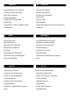
F SOMMAIRE GB CONTENTS RACCORDEMENT ÉLECTRIQUE ELECTRICAL WIRING CONSEILS D’INSTALLATIONS INSTALLATION ADVICE POSE DE L’APPAREIL FITTING THE APPLIANCE FONCTIONNEMENT OPERATION CONSEILS D’UTILISATIONS USEFUL HINTS ENTRETIEN MAINTENANCE GARANTIE ET SERVICE APRÈS-VENTE GUARANTEE AND AFTER-SALES-SERVICES REMARQUES REMARKS D I INHALT CONTENUTI NETZANSCHLUSS COLLEGAMENTO ELETTRICO MONTAGEHILFEN CONSIGLI DI INSTALLAZIONE MONTAGE DES GERÄTES POSA DELL’ APPARECCHIO BETRIEB DES GERÄTES
F Nous vous remercions de la confiance que vous nous avez accordée en choisissant un appareil de la gamme ROBLIN. Celui-ci a fait l’objet de toute notre attention dans sa conception et sa réalisation. Afin qu’il vous donne entière satisfaction, nous vous recommandons de lire avec attention cette notice qui vous expliquera comment l’installer, l’utiliser et l’entretenir dans les meilleures conditions. La présente notice d’emploi vaut pour plusieurs versions de l’appareil.
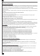
F Les enfants doivent être surveillés pour s’assurer qu’ils ne jouent pas avec l’appareil. 3 POSE DE L’APPAREIL. Montage et raccordement doivent être réalisés par un installateur* qualifié. (*) Le non-respect de cette condition entraîne la suppression de la garantie du constructeur et tout recours en cas d’accident. Attention: prendre bien soin d’employer les chevilles adaptées au support, se renseigner au près des fabricants, effectuer un scellement si nécessaire.
F a- Fixer le support (Rep.4) du déflecteur sur la fixation du haut de conduit, le déflecteur est fixé avec les mêmes vis que le support de haut de conduit (Fig.7, rep. 2). Inserer latéralement les rallonges raccord (Rep.G) sur le déflecteur (Rep. R). S'assurer que la sortie des rallonges raccord se trouve au niveau des ouies du conduit aussi bien en horizontal qu'en vertical. b- Installer un tuyau de diamètre approprié (Non fourni) entre la sortie de l’appareil et à l’entrée du déflecteur.
F (5 ).F c) Fonctions complémentaires : • Vitesse intensive temporisée Pour obtenir une bonne efficacité d’évacuation, nous vous conseillons en début de cuisson une période de fonctionnement en position intensive. Elle créera un flux d’air permettant de capter les premières fumées ou vapeurs dès leur apparition. Pour cette fonction il convient de suivre la procédure suivante : - Mettre le moteur en marche (touche 2), puis sélectionner à l’aide des touches (+) et (-) la vitesse souhaitée pendant la cuisson.
F • Configuration réception télécommande : Votre hotte est programmée pour fonctionner sans réception télécommande. Si vous souhaitez l’utiliser avec la télécommande, vous devez impérativement la configurer suivant la procédure suivante : Moteur et éclairage éteints, appuyer sur la touche 1 (éclairage) jusqu’au clignotement de la led 1 : Deux clignotements de la led 1 indiquent que la télécommande est activée. Un clignotement de la led 1 indique que la télécommande est désactivée.
F • Débrancher complètement l’appareil. • Exigez toujours l’utilisation de pièces de rechange d’origine. La non observation de cette prescription peut compromettre la sécurité de l’appareil. • Lors de la commande de pièces détachées, rappeler le numéro de l’appareil inscrit sur la plaque signalétique située à l’intérieur de la hotte. • Seule la facture d’achat de l’appareil fera foi pour l’application de la garantie contractuelle.
GB Thank you for buying a ROBLIN product which has been manufactured to the highest quality standards to meet your requirements. We recommend you carefully read this booklet in which you will find instructions for installation, hints for use and maintenance. The Instructions for Use apply to several versions of this appliance. Accordingly, you may find descriptions of individual features that do not apply to your specific appliance.
GB green / yellow : earth blue : neutral brown : live As the colours of the wires in the mains lead of this appliance may not correspond with the coloured markings identifying the terminals in your plug, proceed as follows. - The wire which is coloured green and yellow must be connected to the terminal in the plug which is or coloured green or green and yellow.
GB - 4 metres with 1 x 90° bend. - 3 metres with 2 x 90° bends. - 2 metres with 3 x 90° bends. The above assumes our 150 mm (6 INS) ducting is being installed. Please note ducting components and ducting kits are optional accessories and have to be ordered, they are not automatically supplied with the chimney hood. IN THE EXTRACTION MODE: a.
GB 4 OPERATION A - EXTRACTION OR RECYCLING :Your cooker hood is supplied in the extraction mode. To use the cooker hood in the recycling mode re-programme the hood as follows: Starting in the recycling mode (the contaminated air passes into the hood through the grease filters and the purifying activated charcoal filter and back out into the kitchen through grilles).
GB with a pre-set stop of the boost speed re-programme the hood as follows: The lights and the fan motor should be switched ‘OFF’ to set the timer. Push the LED button ‘-’ until the LED lights will flash : One flash of the LED lights 2,3, and 4 = function is switched ‘OFF’. Two flashes of the LED lights 2,3, and 4 = function is switched ‘ON’. While the 5 minutes timer is running, It is available to stop immediately the boost speed by pressing the led button 5.
GB life. These batteries must be disposed of properly and could explode if damaged or exposed to heat. Do not dispose of on fire. Dispose of batteries in the appropriate sort container to protect the environment. 5 USEFUL HINTS • To obtain the best performance we recommend you to switch ‘ON’ the cooker hood a few minutes (in the boost setting) before you start cooking and you should leave it running for approximately 15 minutes after finishing.
GB To remove and replace the metal grease filters • Remove the metal grease filters one at a time by releasing the catches on the filters; the filters can now be removed. • The metal grease filters should be washed, by hand, in mild soapy water or in a dishwasher. • Allow to dry before replacing. Active Charcoal Filter : The charcoal filter cannot be cleaned. The filter should be replaced at least every three months or more frequently if the hood is used for more than three hours per day.
D Wir danken Ihnen für Ihre Kaufentscheidung und das Vertrauen, welches Sie mit dem Kauf dieses ROBLIN-Produktes bewiesen haben. Dieses Gerät wurde mit einem hohen Maß an Kreativität entwickelt und mit größter Sorgfalt gefertigt. Um volle Zufriedenheit mit Leistung und Funktion dieser Dunstesse zu erlangen und zu erhalten, empfehlen wir dringend, sowohl die Montage-anweisung sorgfältig zu beachten und danach zu arbeiten als auch die “ Gebrauchs- und Wartungshinweise ” aufmerksam zu lesen und anzuwenden.
D Achtung ! Bitte beachten Sie bei der Montage das Gewicht der kompletten Dunstesse. Die Tragfähigkeit der Decke oder alternativ der Trägerplatte für diese Zugbelastung muss vor der Montage geprüft und gegebenenfalls durch die Anbringung von geeigneten Befestigungs-oder Stabilisierungselementen hergestellt werden. Kann eine hinreichende Tragfähigkeit nicht sichergestellt werden, ist von einer Montage abzusehen. An der Wand eine vertikale Linie 1 (Abb.
D wieder schließen. • Umluftbetrieb a- Den Umluftadapter R an den Oberkamin hängen, der Umluftadapter wird mit den gleichen Schrauben als die Schrauben für die Oberkaminstütze (Abb. 7 - Pos. 2) befestigt. Die Verlängerungen Pos. G beim Anschluss Pos. R seitlich einfügen. Überprüfen, ob die Verlängerungen Pos. G mit den entsprechenden Kaminstützen sowohl horizontal wie auch vertikal übereinstimmen.
D Gebläse : Wird durch Druck auf die Schaltertaste 2 (Gebläse) eingeschaltet. Die Gebläse-Leistung kann mittels der >>Stufe: Schaltertaste + << und der >>Stufe: Schaltertaste - <<, durch kurzzeitigen oder andauernden Druck auf die entsprechenden Schaltertasten modifiziert werden, bis die gewünschte Stufe erreicht ist.
D LED 2, 3 und 4 blinken „3 mal“ wenn 15 Minuten Nachlaufzeit programmiert ist. Fettfilter – Sättigungsanzeige : Nach 200 Stunden Betriebszeit der Esse wird durch „kurzes Blinken“ der LED 1 angezeigt, daß die Fettfilter gesättigt sind.( Siehe Wartungsabschnitt ). Nach dem Reinigen der Fettfilter erfolgt „ Reset „ auf „Null „ nach folgendem Schema: Motor und Beleuchtung müssen abgeschaltet sein. Die Schaltertaste (+) ca. 3 - 4 Sekunden gedrückt halten.
D Bei dem Einbau des Gerätes wurde besonders die Wartungs-Freundlichkeit berücksichtigt. • Herausnehmen des Metallfilters : Es ist unerläßlich, diese Filter REGELMÄßIG falls notwendig auch in kurzen Intervallen, mit der Hand (lauwarmes Wasser mit Waschmittel und Spülen) oder in der Geschirrspülmaschine zu REINIGEN. Diese Maßnahmen vermindern die Brandgefahr (starke Fettrückstände sind leicht brennbar). • Gehäuse. Keine nassen Tücher für die Reinigung der Oberflächen der Dunstesse verwenden.
I La ringraziamo per la fiducia accordataci nell’aver scelto un prodotto della gamma ROBLIN. Questo apparecchio è stato studiato e realizzato con la massima cura, secondo i più alti criteri di qualità. Le raccomandiamo di leggere attentamente questo opuscolo, nel quale troverà le istruzioni per installare, utilizzare e conservare al meglio il suo apparecchio ed ottenere dal suo acquisto il massimo dei benefici. Questo libretto di istruzioni per l’uso è previsto per più versioni dell’ apparec-chio.
I dovuta alla perforazione ed al fissaggio. 1) Tracciare Sulla parete una linea verticale fino al soffitto, al centro della zona prevista per il montaggio della cappa (Fig. 1 & 2 , Rif. 1); questa operazione serve ad effettuare l’allineamento verticale delle diverse parti della cappa. 2) Appoggiare una delle staffe (2) sulla parete a circa 1 o 2 mm dal soffitto o dal limite superiore, allineando il suo centro (intagli) sulla linea verticale. Segnare sulla parete i due fori asolati della staffa.
I alimentazione sia correttamente inserito nella presa dell’Aspiratore (Fig. 4). Inserire le spine elettriche (vedi paragrafo collegamento elettrico). Verificare il corretto funzionamento di illuminazione, accensione del motore, cambio delle velocità. d- Togliere i filtri metallici e posizionare le cartucce a carbone attivo negli appositi alloggiamenti, esercitando una pressione sulle linguette A (Fig. 4). e- Camino superiore: Allargare leggermente le due falde laterali del camino (Fig. 7 - Rif.
I Premere il tasto (-) : Un lampeggio delle led 2, 3 e 4 indica che la funzione è disattivata. Due lampeggi delle led 2, 3 et 4 indicano che la funzione è attivata. E’ possibile interrompere manualmente la velocità intensiva prima dello scadere dei 5 minuti premendo il tasto 5 (velocità intensiva). Durante la temporizzazione, l’indicazione di saturazione dei filtri è disattivata.
I Non disperdere le pile nell’ambiente, depositarle negli appositi contenitori. 5 CONSIGLI DI UTILIZZO • Per ottenere il massimo dell’efficacia per quanto riguarda l’assorbimento dei fumi o del vapore, mettere in funzione l’apparecchio prima e dopo la cottura degli alimenti ; per le preparazioni che producono poco vapore, utilizzare di preferenza le velocità più basse. • IMPORTANTE : NON CUCINARE MAI PIATTI ALLA FIAMMA SOTTO LA CAPPA. Non lasciate mai fiamme libere sotto una cappa funzionante.
I 8 NOTE Quest’apparecchio é conforme alla norma europea sulla bassa tensione 2006/95/CE relativaalla sicurezza elettrica e alle norme europee: 2004/108/CE relativa alla compatibilità elettromagnetica e C.E.E. 93/68 relativa alla marcatura CE. Quando ad un prodotto è attaccato il simbolo del bidone con le ruote segnato da una croce, significa che il prodotto è tutelato dalla Directiva Europea 2003/96/EC.
E Le agradecemos la confiancia que nos participan ustedes elegiendo un aparato de la gama ROBLIN quien fue el objeto de toda nuestra atención en su concepción y realisación. Para que les de entera satisfacción, les aconsejamos ustedes leer con atención esta noticia que les explicara ustedes como instalarle, utilisarle y mantenerle en las mejores condiciones. Esta noticia de instrucciones esta utilizada para varios aparatos. Puede contener descripciones de accessorios no utilizados en su proprio aparato.
E sensoriales o mentales estan reducidas, ni por personas que no tienen la experiencia o el conocimiento de este tipo de aparatos a menos de estar bajo el control y la formación de personas responsables de ella securidad. Las niños deben ser cuidados para asegurarse que no juegan con el aparato. 3 INSTALACION DEL APARATO La instalación y conexión debe ser realizada por un instalador autorizado *.
E los tornillos. 5) Conexión aspirante o filtrante •Conexión aspirante: a- Poner en sitio la valvula anti rechazo ( Rep.8) en la salida del aparato ( Rep.6) y instalar el tubo flexible (Fig. 5) de la evacuación externa y la salida del aparato (Rep. 6). Fijar todo junto con abrazaderas o con cinta adhesiva apropriadas. b- Conectar las enchufes. c- Ensanchar ligeramente las faldas laterales de la chimenea (Fig. 5 - Rep. 7a) y engancharlas detras de las placas 2 dejandolas volver a su posición inicial.
E Un parpadeo de los 5 LEDS indicará la memorización de la puesta en marcha del modo evacuación exterior. B) FUNCIONES DE BASE Alumbrado: Su puesta en marcha se efectúa apretando el botón 1 (luz). El LED 1 mostrará si el alumbrado está o no en marcha. Motor: Su puesta en marcha se efectúa apretando el botón 2 (motor).
E INDICACIÓN DE SATURACIÓN DE LOS FILTROS METÁLICOS : Al cabo de 200 horas de funcionamiento un breve parpadeo del LED 1 indicará que los filtros metálicos deben limpiarse (ver párrafo de mantenimiento). Para acceder a la puesta a cero de la función de aviso de saturación de filtros, la luz deberá estar apagada y el motor parado. Apretar el botón (+) durante 3 ó 4 segundos. El parpadeo de los LEDS 2, 3, 4 y 5 confirmará la puesta a cero.
E Limpiar regularmente la carcasa utilizando detergentes no abrasivos y una esponja ligeramente húmeda. No utilice jamás esponjas o trapos empapados. No introduzca ningún objeto, ni las manos, en la apertura para la evacuación del aire. . Conducto de evacuación Verificar cada 6 meses el buen flujo del aire viciado. Observar las prescripciones reglamentarias locales sobre la evacuación del aire viciado. .
NL Wij danken U voor de goede keuze en het vertrouwen dat U ons, ROBLIN specialist op het gebied van afzuigkappen geeft, om in de toekomst met een afzuigkap uit het gamma ROBLIN te werken. Wij raden U aan om alvorens U de ROBLIN afzuigkap in werking zet deze handleiding aandachtig te lezen. Deze gebruiksaanwijzing geldt voor verschillende uitvoeringen van het apparaat. Het is mogelijk dat er een aantal kenmerken worden beschreven die niet van toepassing zijn op uw apparaat.
NL (*) Het niet respecteren van deze voorwaarde houd in dat de garantie en de verantwoordelijkheid van de fabrikant vervalt. Let op! Zorg dat u pluggen gebruikt die geschikt zijn voor het type wand. Vraag advies aan de fabrikant. Indien nodig vastmetselen. Wij zijn niet aansprakelijk in geval van defecte bevestiging veroorzaakt door de in de muur gemaakte boorgaten en de gebruikte pluggen.
NL bijgeleverde schroeven (12c) 2,9 x 9,5. d- Onderstuk van de schouw : De twee zijplaten van de schouw enigszins openen Fig. 5 - Rep. 7b, ze vasthaken tussen het bovenstuk van de schouw en de wand en ze weer zo ver mogelijk sluiten. Aansluiting voor filtering a- Installeer het verbindingsstuk 4 in de draagbeugel 2. Verzeker u ervan dat de uitlaat van de verlengstukken van het verbindingsstuk G zowel horizontaal als verticaal correspondeert met de mondstukken van de schouw. b- Sluit het 150 mm.
NL Motor : Zet de kap in dienst door op toets 2 te drukken, met behulp van de – en + toets regelt U het afzuigvermogen van de afzuigkap. Door één van deze toetsen ingedrukt te houden zal de afzuigkap meer of minder vermogen krijgen. Led 2 = minimum afzuigvermogen ( bij weinig rook & damp) Led 2 & 3 = normaal afzuigvermogen Led 2 & 3 & 4 = hoog afzuigvermogen ( bij veel rook & damp) Door op toets 5 te drukken zet U de afzuigkap in de intensief stand, het volle vermogen wordt nu gebruikt.
NL Instellingen voor gebruik van afstandbediening : De wasemschouw is uitgevoerd met een sensor voor een afstandbediening. Om deze mogelijkheid in te stellen, kan de functie worden geactiveerd: Door led ‘1’ (verlichting) in te drukken terwijl de motor en de verlichting uit staan, totdat led 1 knippert, dit geeft aan dat de functie in werking is. Eén keer knipperen van led 1 betekent functie staat uit - ‘OFF’. Twee keer knipperen van led 1 betekent functie aan –‘ON’.
NL kan de aansluitingen van het apparaat controleren. • Indien de stroomkabel beschadigd is, kan deze uitsluitend worden vervangen door een erkende installateur, aangezien speciaal gereedschap vereist is. • Schakel in ieder geval de stroomtoevoer af. • Indien u onderdelen wilt bestellen dient het nummer van het apparaat vermeld te worden. Dit nummer bevindt zich op het identificatieplaatje dat op de afzuigkap geplaatst is.
UK ELECTRICAL CONNECTION The wires in this mains lead are coloured in accordance with the following code: ELECTRICAL REQUIREMENTS Any permanent electrical installation must comply with the latest I.E.E. Regulations and local Electricity Board regulations. For your own safety this should be undertaken by a qualified electrician e.g. your local Electricity Board, or a contractor who is on the roll of the National Inspection Council for Electrical Installation Contracting (NICEIC).
PURPLE PINK L M ECLAIRAGE HALOGENE HALOGEN LIGHTING HALOGEN BELEUCHTUNG 2 x 20 W - 12 V Blue White Brown Black M L F N 10 µF 400 V Green-Yellow 220 - 60Hz FERNBEDIENUNG RECEPTEUR INFRAROUGE REMOTE CONTROL M 350 W 220 - 240 V 50Hz ELEKTRONISCHE STEUERUNG BOITIER COMMANDE PUSH BUTTON PANEL AZUR - AZUR - AZUR BLAU BLACK - NOIR- SCHWARZ BLUE - BLEU - BLAU BROWN - BRUN - BRAUN GREEN YELLOW - VERT JAUNE - GRÜN GELB GREY - GRIS - GRAU LIGHT BLUE - BLEU CLAIR - HELL BLAU PINK - ROSE - ROSA PURPLE - M
650 min. 500 A3 69 23 min. 680 - max.
16 7a 7b 1 115 328 2 9 H mini.
3 12a + + + 3a Vr Vr 3b A5
4 5 7a 7b A6
Halogen Beleuchtung Halogen Lighting Eclairage halogène Alogene Luci Alógenas Luz Halogeen Verlichting 2 x 20 W - 12 V G4 12V 20W A7
6 2 978 115 4 G 7a R 7b 7 A A8
8 2 1 3 LR03 / AAA / 1,5V ACCESSOIRES ACCESSORIES ZUBEHÖRE A9 ACCESSORI ACCESORIA ACCESSOIRES
(2) 600 13MC055 364,5 x 264 x 8 mm (3) 900 (4) 1200 13MC064 364,5 x 282 x 8 mm A10
Plaque Signalétique de la hotte Rating plate of the cookerhood Typenschild im Inneren der Dunstesse Etichetta all'interno della cappa Etiqueta de la campana Typeplaatje van de afzuigkap Modèle Model Modell Modello Modelo Model Numéro de série Serial number Seriennummer Numero di serie Numero de serie Serienummer A11
## FRANKE France S.A.S. ## 25 Rue des Rosiers - Sainte Cécile B. P. 93356 50800 VILLEDIEU-LES-POËLES - France Tél. 02 33 91 26 50 - Fax 02 33 51 54 79 - e-mail : com.france@roblin.fr For outside France : Tel. +33 (0)2 33 91 26 57 - Fax. : +33 (0)2 33 51 54 79 e-mail : com.export@roblin.