RS-LiDAR-16 User Manual 1
RS-LiDAR-16 User Manual Revision History Revision Content Date Edited by 1.0 Initial release 2017-03-01 RD 3.0 Fill in the content according to RS-LiDAR-16 1.0 hardware. 2017-05-10 RD 3.1 Modify the relationship between laser channel and vertical angle 2017-06-13 PD 3.2 Update the content according to RS-LiDAR-16 2.0 hardware 2017-07-17 PD 2017-08-10 PD 2017-08-23 PD 2017-09-16 PD 2017-12-05 PD 2018-02-05 PD Add the timestamp calculation method for every point 3.
RS-LiDAR-16 User Manual 4.1 Add the sensor clean instruction 2018-08-04 PD 2019-04-25 PD 2019-07-10 PD Add the RSVIEW compatible instruction Add the LiDAR cable route instruction 4.
RS-LiDAR-16 User Manual Add GPS interface PIN definition of the V4.0 version LiDAR’s interface box 4.3.1 Update electrical interface diagram Add "LiDAR" to the network wiring definition 4.3.2 Correct some description faults 2019-12-11 PD 2020-02-18 PD Add LiDAR mechanical installation suggestion Update download address of RSView Add LiDAR dimension diagram Add footnote for specification in chapter 3 4.3.
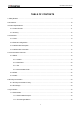
RS-LiDAR-16 User Manual TABLE OF CONTENTS 1 Safety Notices........................................................................................................................................................ 9 2 Introduction...........................................................................................................................................................10 3 Product Specifications......................................................................................................
RS-LiDAR-16 User Manual 7.1.3 Strongest, Last and Dual Returns............................................................................................. 30 7.1.4 Return Mode Flag.........................................................................................................................30 7.2 Phase Lock............................................................................................................................................... 31 8 Point Cloud...............................
RS-LiDAR-16 User Manual C.4 Visualize Streaming Sensor Data.........................................................................................................50 C.5 Capture Streaming Sensor Data to PCAP File.................................................................................. 51 C.6 Replay Captured Sensor Data from PCAP File................................................................................. 52 C.7 RS-LiDAR-16 Factory Firmware Parameters Setting..............................
RS-LiDAR-16 User Manual Terminologies MSOP Main Data Stream Output Protocol DIFOP Device Info Output Protocol UCWP User Configuration Write Protocol Azimuth Horizontal angle of each laser firing Timestamp The marker that records the system time Header The starting part of the protocol packet Tail The ending part of the protocol packet 8
RS-LiDAR-16 User Manual Congratulations on your purchase of a RS-LiDAR-16 Real-Time 3D LiDAR Sensor. Please read carefully before operating the product. Wish you a pleasurable product experience with RS-LiDAR-16. 1 Safety Notices To reduce the risk of electric shock and to avoid violating the warranty, do not open sensor body. Laser safety - The laser safety complies with IEC 60825-1:2014. Read Instructions - All safety and operating instructions should be read before operating the product.
RS-LiDAR-16 User Manual 2 Introduction RS-LiDAR-16, launched by RoboSense, is the first of its kind in China, world leading 16-beam miniature LiDAR product. Its main applications are in autonomous driving, robot-environment perception and UAV mapping. RS-LiDAR-16, as a solid-state hybrid LiDAR, integrates 16 laser/detector pairs mounted in a compact housing.
RS-LiDAR-16 User Manual 3 Product Specifications1 3.1 Product Format Table 1: Product Parameters. Time of Flight Distance Measurement 16 Channels Measurement Range: 40cm to 150m (on 20% reflectivity target)2 Accuracy: ±2cm (typical, refer to Figure 2)3 Sensor Field of View (Vertical): ±15.0° (30° in total) Angular Resolution (Vertical): 2° Field of View (Horizontal): 360° Angular Resolution (Horizontal/Azimuth): 0.1°(5Hz) to 0.
RS-LiDAR-16 User Manual Power Consumption:12 W (typical)4 Operating Voltage: 9-32 VDC (with Interface Box and Regulated Power Supply) Mechanical/ Electrical/ Operational Weight: 0.87 Kg (without cable) Dimensions: 109 mm Diameter X 80.7 mm Height Environmental Protection: IP67 Operation Temperature: -30 ℃ to +60 ℃5 Storage Temperature: -40 ℃ to +85 ℃ 3.2 Accuracy Figure 2: The Relation between accuracy and distance of target object.
RS-LiDAR-16 User Manual 4 Connections 4.1 Power When equipped with an interface box, the device requires a voltage range of 9-32 VDC, and 12 VDC is recommended. If the interface box is not used for the LiDAR, a regulated 12 VDC must be used, while the V4.0 and later versions of the LiDAR integrate the wide-voltage function internally, so you can continue to use 9-32 VDC. The power consumption of the device is about 12 W (typical). 4.
RS-LiDAR-16 User Manual PIN Wire Color Function 1 Red +12V 2 Yellow +12V 3 White GROUND 4 Black GROUND 5 Green GPS PULSE 6 Blue GPS REC 7 Brown LiDAR Ethernet RX- 8 Brown white LiDAR Ethernet RX+ 9 Orange LiDAR Ethernet TX- 10 Orange white LiDAR Ethernet TX+ Figure 4: Aviation Plug PIN Number. 4.3 Interface Box Description The Interface BOX is connected to the RS-LiDAR-16 by default.
RS-LiDAR-16 User Manual PIN No. V4.0 and later versions Other versions 1 GPS PULSE GPS REC 2 +5V GPS PULSE 3 GND GND 4 GPS REC NC 5 GND NC 6 NC +5V Figure 5: Interface definition on Interface Box. Note: When RS-LiDAR-16 connects its grounding system with an external system, the external power supply system should share the same grounding system with that of the GPS. On the Interface BOX, the red light indicator means standard power input, and the green one means standard power output.
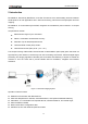
RS-LiDAR-16 User Manual 4.4 Interface Box Connection Figure 6: Interface Box connection diagram.
RS-LiDAR-16 User Manual 5 Communications Protocols RS-LiDAR-16 adopts UDP protocol and communicates with computer through 100Mbps Ethernet. There two different kinds of UDP output packets: MSOP packets and DIFOP packets. The UDP protocol packet in this manual is of 1290 byte long, and consists of a 1248-bytes- payload and a 42-byte header. The IP address and port number of RS-LiDAR-16 is set in the factory as shown in the Table 2, but can be changed by the user as needed.
RS-LiDAR-16 User Manual 5.1 MSOP I/O type: device output data, computer parse data. Default port number is 6699. MSOP outputs data information of the 3D environment in packets. Each MSOP packet is 1248 bytes long and consists of reported distance, calibrated reflectivity values, azimuth values and a time stamp. Each RS-LiDAR-16 MSOP packet payload is 1248 byte long and consists of a 42-byte header and a 1200-byte data field containing twelve blocks of 100-byte data records and a 6-byte tail.
RS-LiDAR-16 User Manual The basic data structure of a MSOP packet for dual return is as shown in Figure 8.
RS-LiDAR-16 User Manual 5.1.2 Data Field Data field comprises data blocks that contain valid measurement data. Each data filed contains 12 blocks. Each block is 100-byte long and is a complete measurement data set. Each data block begins with a 2-byte start identifier “0xffee”, then a two-byte azimuth value (rotational angle). Each azimuth value records 32 sets of channel data reported by the 16 laser channels for two sequence.
RS-LiDAR-16 User Manual In the example below, N=1. // First, adjust for a rollover from 359.99° to 0° If (Azimuth[3] < Azimuth[1]) Then Azimuth[3]:= Azimuth[3]+360; Endif; // Perform the interpolation Azimuth[2]:=Azimuth[1]+((Azimuth[3]-Azimuth[1])/2); // Correct for any rollover over from 359.99° to 0° If (Azimuth[2]>360) Then Azimuth[2]:= Azimuth[2]-360; Endif 5.1.2.
RS-LiDAR-16 User Manual 5.1.3 Tail The tail is 6 bytes long, with 4 bytes unused and reserved for information, and the other 2 bytes as: 0x00, 0xFF. 5.1.4 Demonstration Data Figure 9: MSOP Packet Display.
RS-LiDAR-16 User Manual Figure 10: 1 cm Resolution Data Block Display. Figure 11: 0.5 cm Resolution Data Block Display.
RS-LiDAR-16 User Manual 5.2 DIFOP I/O type:device output, computer read. Default port number is 7788. DIFOP is a protocol that reports and outputs only device information including the device serial number, firmware version, driver compatibility, internet setting, calibration data, electrical machine setting and operation status, fault detection information to users. It is a viewer for users to get comprehensive details about the device.
RS-LiDAR-16 User Manual Tail 16 Operation status (STATUS) 313 18 17 Reserved 331 11 18 Fault diagnosis (FALT_DIGS) 342 40 19 GPRMC 382 86 20 Corrected static (COR_STATIC) 468 697 21 Corrected vertical angle (COR_VERT_ANG) 1165 48 22 Reserved 1213 33 23 Tail 1246 2 Note: The Header (the DIFOP identifier) in the table above is 0xA5, 0xFF, 0x00, 0x5A, 0x11, 0x11, 0x55, 0x55, among which the first 4 byte 0xA5,0xFF,0x00,0x5A is the sequence to identify the packet.
RS-LiDAR-16 User Manual which, the first 4 bytes 0xAA, 0x00, 0xFF, 0x11 forms the sequence to identify the packet. Statement: RS-LiDAR-16 doesn’t RTC system to support operation while power is off. In the case of no GPS or GPS signal, it is imperative to write time into the device through a computer, or it will use a default system time for clock. Refer to Appendix B of this manual for details on Ethernet, Time, Motor Rotation Speed and Motor Phase Lock.
RS-LiDAR-16 User Manual DIFOP Port(port3) 8899 0x22C3 2 DIFOP Port(port4) 8899 0x22C3 2 FOV starting angle 0 0x0000 2 FOV end angle 12000 0x2EE0 2 Year:2017 0x11 Month:3 0x03 Day:10 0x0A Hour:9 0x09 Minute:45 0x2D Second:30 0x1E Millisecond: 100 0x00,0x64 Microsecond: 200 0x00,0xC8 90 0x005A UTC_TIME Motor Phase Lock 10 2 While setting the device and computer according to this protocol, it is imperative to set all the information listed in the table above.
RS-LiDAR-16 User Manual 6 GPS Synchronization RS-LiDAR-16 supports external GPS receiver connections. With GPS connections, we can synchronize the RS-LiDAR-16 system time and pack the GPRMC message into DIFOP packets. 6.1 GPS Synchronization Theory The GPS receiver keeps generating synchronization Pulse Per Second (PPS) signal and GPRMC message and send them to the sensor.
RS-LiDAR-16 User Manual PIN +5 V can supply the power for GPS module. (Please do not connect the GPS into the +5 V PIN if the GPS is 3.3 V power supply. Also please do not input the power into the +5 V PIN because the PIN is an output.) PIN GND provide the ground connection for GPS module. The GPS module should set to 9600 bps baud rate, 8-bit data bit, no parity and 1 stop bit. RS-LiDAR-16 only read the GPRMC message from GPS module.
RS-LiDAR-16 User Manual 7 Key Features 7.1 Return Mode 7.1.1 Return Mode Principle RS-LiDAR-16 supports multiple return modes: Strongest return, Last return and Dual return. When set to dual return mode, the details of the target will be enhanced, and the number of points is twice than that of a single return. Due to the divergence of the beam, it is possible to generate multiple laser returns with one laser emission. When the laser pulse is emitted, its light spot gradually becomes larger.
RS-LiDAR-16 User Manual Table 9: Return Mode and Flag Byte Comparison Table. Flag Byte Return Mode 00 Dual Returns 01 Strongest Return 02 Last Return 7.2 Phase Lock When using multiple RS-LiDAR-16 sensors in proximity to one another, users may observe interference between them due to one sensor picking up a reflection intended for another. To minimize this interference, RS-LiDAR-16 provides a phase-locking feature that enables the user to control where the lase firings overlap.
RS-LiDAR-16 User Manual 8 Point Cloud 8.1 Coordinate Mapping RS-LiDAR-16 exports data packet that contains azimuth value and distance data. But to present a 3-dimensional point cloud effect, a transformation of the azimuth value and distance data into x, y, z coordinates in accordance to Cartesian Coordinate System is necessary.
RS-LiDAR-16 User Manual objects. Therefore, in a rectangular environment, the section lines of the conical surfaces and the rectangular planes are hyperbolas as shown in Figure 15. Figure 15:Contour lines plotted on X, Z coordinates. Figure 16: RS-LiDAR-16 Scanning Illustration. The hyperbolas contour lines phenomenon can also be explained by transforming polar coordinates into orthogonal coordinates. As shown in Figure 17, we deduced the function of a hyperbolas z2 x2 1 ( y tan( )) 2 y 2 .
RS-LiDAR-16 User Manual 9 Laser Channels and Vertical Angles Figure 18:RS-LiDAR-16 Laser Channels and Vertical Angles. RS-LiDAR-16 has a vertical field of view of -15°to +15°with an interval of 2°. The 16 laser heads also called as 16 channels. The laser channels and their designated vertical angles are as shown in the Table 10. Table 10: Laser Channel Number and Their Designated Vertical Angle. Laser Channel No.
RS-LiDAR-16 User Manual 12 +9 13 +7 14 +5 15 +3 16 +1 Every sequence of 16 laser firings consumes 55.5 μs.
RS-LiDAR-16 User Manual 10 Calibrated Reflectivity RS-LiDAR-16 produces calibrated reflectivity data of objects. Reflectivity of object is largely determined by the property of objects. Reflectivity therefore is an important information for LiDAR to distinguish objects. RS-LiDAR-16 reports reflectivity values from 0 to 255 with 255 being the reported reflectivity for an ideal reflector.
RS-LiDAR-16 User Manual configuration_data/curves.csv). The calculate code is suggested calibrateIntensity( ) in rawdata.cc from RS-LiDAR-16 ROS package. to refer to the function Note 1: Because of the firmware upgrade, the calculation of the intensity in the calibrateIntensity() function has been adjusted for several times, and the new code is backward compatible with the earlier firmware. There are three modes to calculate the reflectivity.
RS-LiDAR-16 User Manual 11 Troubleshooting This section provides detail on how to troubleshoot your sensor.
RS-LiDAR-16 User Manual Are excessive broadcast packets from another service being received by the sensor? This can slow the sensor down Is the computer fast enough to keep up with the packet flow coming from the sensor? Remove all network devices and test with a computer directly connected to the sensor. Check baud rate is 9600 and serial port set to 8N1 (8 bits, no parity, 1 stop bit). GPS not synchronizing No data via router Check the signal level is 3.
RS-LiDAR-16 User Manual Appendix A ▪ Point Time Calculate In a MSOP packet, there are 12 blocks, each block has two sequence for the whole 16 laser firings, so in a MSOP packet, there are 24 groups for the whole 16 laser firings. All sixteen lasers are fired and recharged every 55.5µs. The cycle time between firing is 2.8µs. There are 16 firings (16 x 2.8µs = 44.8 µs) followed by a short period of 10.7µs. Therefore, the timing cycle to fire and recharge all 16 lasers is given by ((16 x 2.8µs) + (1 x 10.
RS-LiDAR-16 User Manual Appendix B ▪ Information Registers Here are definitions and more details on information registers as mentioned in Section 5. B.1 Motor(MOT_SPD) MOT_SPD (2 bytes in total) Byte No. byte1 byte2 Function MOTOR Register description: (1) This register is used to set the rotation direction and rotation speed. (2) The data storage format adopts big endian format.
RS-LiDAR-16 User Manual (3) MAC_ADDR is the LiDAR MAC Address. (4) port1~port4 signals the number of ports. Port1 is MSOP Port Number of LiDAR for outputting packet and port2 is the destination PC Port Number for receiving MSOP packet. Port3 is DIFOP Port Number of LiDAR for outputting packet and port4 is the destination PC Port Number for receiving DIFOP packet. By default, Port1 and port2 are same, port3 and port4 are same. B.3 FOV Setting (FOV SET) FOV SET(4bytes in total) No.
RS-LiDAR-16 User Manual B.6 Bottom Board Firmware (BOT_FRM) BOT_FRM(5bytes in total) No. byte1 byte2 Byte3 Function Byte4 Byte5 BOT_FRM Register description: If our top board firmware revision is B7R14V4_T1_F, then BOT_FRM will output 07 14 04 01 F0. In the output, the A represents release version Application, while the F represents factory version Factory. B.7 Corrected Vertical Angle (COR_VERT_ANG) COR_VERT_ANG(48 bytes in total) Byte No. byte1 Function Byte No.
RS-LiDAR-16 User Manual convert to decimal: byte1 = 0, byte2 = 39, byte3 = 16. cor_pitch_9: (0*2562+ 39*256+16) *0.0001 = 1°. B.8 Serial Number(SN) SN(6 bytes in total) Byte No. 1byte 2byte 3byte Function 4byte 5byte 6byte SN The Serial Number of each device adopts the same format as the MAC_Address, namely, a 6-byte hexadecimal number. B.9 Software Version(SOFTWARE_VER) SOFTWARE_VER(2 bytes in toatal) Byte No.
RS-LiDAR-16 User Manual (2) Month set_month Byte No. bit7 bit6 bit5 bit4 Function reserve reserve reserve reserve bit3 bit2 bit1 bit0 set_month[3:0]:1~12 month (3) Day set_day Byte No. bit7 bit6 bit5 Function reserve reserve reserve bit4 bit3 bit2 bit1 bit0 set_day[4:0]:1~31 day (4) Hour set_hour Byte No. bit7 bit6 bit5 Function reserve reserve reserve bit4 bit3 bit2 bit1 bit0 set_hour[4:0]:0~23 hour (5) Min set_min Byte No.
RS-LiDAR-16 User Manual (8) μs set_μs Byte No. bit15 bit14 bit13 bit12 bit11 bit10 Function reserve reserve reserve reserve reserve reserve Byte No. bit7 bit6 bit5 bit4 bit3 bit2 bit1 bit0 byte6 byte7 byte8 Function bit9 bit8 us[9:8] set_μs[7:0] Note:set_μs[9:0] value:0~999 B.11 STATUS Status (18bytes in total) Byte No. byte1 Function byte2 byte4 Idat1_reg Byte No. byte9 Function Vdat_12V_M_reg Byte No.
RS-LiDAR-16 User Manual The unit above is volt (V). B.12 Fault Diagnosis Fault Diagnosis (40bytes in total) Byte No. byte1 byte2 byte3 byte4 Function Byte No. Function byte6 byte7 byte8 byte14 byte15 byte16 reserve byte9 Function Byte No. byte5 byte10 reserve byte17 byte11 cksum_st byte18 temperature1_reg Byte No. byte25 byte26 Function temperature5_reg Byte No.
RS-LiDAR-16 User Manual temperature4 represent the top board temperature. Each temperature register contains 2 bytes to be temperature_reg[15:0]. temperature_reg[2:0] is invalid. temperature_reg[15:3] is temperature value, while temperature_reg[15] is symbol flag. The temperature formula is as below: Temperature5 represents bottom board temperature. The temperature register contains 2 bytes to be temperature_reg[15:0]. temperature_reg[15:12] is invalid.
RS-LiDAR-16 User Manual Appendix C ▪ RSView This appendix gets you started with RSView. It shows you how to use the application to acquire, visualize, save, and replay sensor data. You can examine sensor data with other free tools, such as Wireshark or tcp-dump. But to visualize the 3D data, use RSView. It’s free and relatively easy to use. The version used this time is RSView3.1.5. C.1 Features RSView provides real-time visualization of 3D LiDAR data from RoboSense LiDAR sensors.
RS-LiDAR-16 User Manual as 192.168.1.102, sub-net mask should be 255.255.255.0. You should make sure that RSView not be shielded by firewall in the computer. C.4 Visualize Streaming Sensor Data 1. Connect the sensor to your computer and power it up. 2. Right Click to start the RSView application with Run as administrator. 3. Click on File > Open and select Sensor Stream (Figure C-1). Figure C - 1: RSView Open Sensor Stream. 4. The Sensor Configuration dialog will appear.
RS-LiDAR-16 User Manual Figure C - 3: Sensor Stream Data Display in RSView . C.5 Capture Streaming Sensor Data to PCAP File 1. Click the Record button when streaming (Figure C-4). Figure C - 4: RSView Record Button. 2. A Choose Output File dialog will pop up. Navigate to where you want the file to be saved and click the Save button (Figure C-5). RSView begins writing packets to your pcap file. (Note: RS-LiDAR-16 sensors generate a lot of data.
RS-LiDAR-16 User Manual 3. Recording will continue until the Record button is clicked again, which stops the recording and closes the pcap file. C.6 Replay Captured Sensor Data from PCAP File To replay (or examine) a pcap file, open it with RSView. You can press Play to let it run, or scrub through the data frames with the Scrub slider. Select a set of 3D rendered data points with your mouse and examine the numbers with a Spreadsheet sidebar. 1. Click on File > Open and select Capture File (Figure C-6).
RS-LiDAR-16 User Manual Figure C - 8: RSView Play Button. 5. To take a closer look at some data, scrub to an interesting frame and click the Spreadsheet button (Figure C-9). A sidebar of tabular data is displayed to the right of the rendered frame, containing all data points in the frame. Figure C - 9: RSView Spreadsheet Tool. 6. Adjust the columns to get a better view of the numbers. If you’ve adjusted columns in Excel, some of this will be familiar.
RS-LiDAR-16 User Manual 8. Click the Select All Points tool. This turns your mouse into a point selection tool (Figure C-12). Figure C - 12: RSView Select All Points. 9. In the 3D rendered data pane use your mouse to draw a rectangle around a small number of points. They will immediately populate the data table (Figure C-13). Figure C - 13: RSView List Selected Points. 10. At any selected point you can save a subset of data frames by doing Spreadsheet>Show only selected elements>Output CSV data. C.
RS-LiDAR-16 User Manual Figure C - 14: RS-LiDAR Information. 3. We can modify the parameters to the ones we want to have, then click Set LiDAR. We need re-power and connect the RS-LiDAR-16 to make the modified parameters valid. After the device connecting again, we can use RSView to see the RS-LiDAR Information again to check if the modification take effect. Figure C - 15: Set LiDAR information.
RS-LiDAR-16 User Manual Attention 1:Please do not power off the sensor when we are setting LiDAR information, it may cause the sensor internal parameters broken. Attention 2: if we modify the MSOP Port or DIFOP parameters above, we need setting the RSView MSOP Port and DIFOP Port according to C.8 section to make RS-LiDAR-16 can be connected correctly. C.
RS-LiDAR-16 User Manual for update, and then click Open to begin the online update process. The online update process would take some time, if the firmware update successfully, it will show “Online Update Successful”. Note: The Config Update option is not available. Figure C - 18: Select the Firmware for Update. Figure C - 19: Online Update successful. C.
RS-LiDAR-16 User Manual Figure C - 20: Fault Diagnosis.
RS-LiDAR-16 User Manual Appendix D ▪ RS-LiDAR-16 ROS Package This appendix describes how to use ROS to view the RS-LiDAZR-16 data. D.1 Prerequisite 1. Download and install Ubuntu 16.04. 2. Please refer the link (http://wiki.ros.org/kinetic/Installation) to install the ROS kinetic version. 3. Download and install libpcap-dev. D.2 Install RS-LiDAR-16 ROS Package 1. Create the work space for ros: cd ~ mkdir -p catkin_ws/src 2. Copy the ros_rslidar_package into the work space ~/catkin_ws/src.
RS-LiDAR-16 User Manual 2. We have provided an example launch file under rslidar_pointcloud/launch to start the node, we can run the launch file to view the real time point cloud data. Open a terminal: cd ~/catkin_ws source devel/setup.bash roslaunch rslidar_pointcloud rs_lidar_16.launch 3. Open a new terminal: rviz Set the Fixed Frame to "rslidar". Add a Pointcloud2 type and set the topic to "rslidar_points": Figure D - 1: Rviz displays point cloud data of RS-LiDAR-16. D.
RS-LiDAR-16 User Manual PAGE 62RS-LiDAR-16 User Manual Appendix E ▪ Dimensions Figure E - 1: Dimension Image of LiDAR.
RS-LiDAR-16 User Manual Appendix F ▪ LiDAR Mechanical Installation Suggestion Please make sure the platform surface used for mount LiDAR is smooth as possible. Please make sure the locating pin on the mount surface do exceed 4mm high. The material of the mount platform is suggested to be aluminum alloy in order to thermolysis.
RS-LiDAR-16 User Manual Appendix G ▪ How to Distinguish the Port Number of MSOP and DIFOP Packets According to the Chapter 5, RS-LiDAR-16 outputs MSOP packets and DIFOP packets. We can use the Wireshark software to filter the MSOP packets or DIFOP packets so that we can know which port number the packets send to. After that we can set the Data Port in the RSVIEW. We first need connect the RS-LiDAR-16 to the PC and power on the RS-LiDAR-16.
RS-LiDAR-16 User Manual Appendix H ▪ Sensor clean H.1 Attention Please read through this entire Appendix H content before clean the RS-LiDAR. Improper handling can permanently damage it. When the sensor is used in a harsh environment, it is necessary to clean the it in time to keep its performance. H.2 Require Materials 1. Clean microfiber cloths 2. Mild, liquid dish-washing soap 3. Spray bottle with warm, clean water 4. Spray bottle with warm, mildly soapy water 5. Isopropyl alcohol H.
RS-LiDAR-16 User Manual