
User Manual

www.veear.eu
User Manual (1.0.14) EasyVR 3 15
IOn
SWITCH
optional
filter
IOn
5V
IN
IOn
Isolated
IN
optocoupler
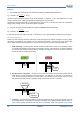
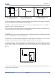
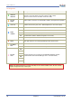
I/O pin connected to a switch
(or switching sensor)
I/O pin connected 5V source
(such as MCU output pin)
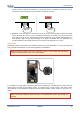
I/O pin with isolated input (for
safety circuits)
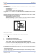
All these circuits assume the EasyVR pin has been configured with an internal pull-up (passive components
value can be adjusted to account for weak or strong pull-up).
Disabling the internal pull-up could be used to put the pin in high-impedance state, for example to
simulate a tri-state or open-drain output port.
Again, you should refer to the manufacturer’s datasheet when interfacing any external components and to
calculate required resistors values or other passive components.
Flash Update
The EasyVR module includes a boot loader that allows to update the firmware and to download new sound
tables or custom grammars to the on-board memory.
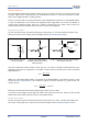
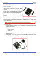
The boot mode is activated by keeping the XM signal to a high logical level at power on or reset. This can
be easily done with a jumper (or switch) taking the signal to a suitable pull-up resistor.
To download a firmware update, a sound table or a custom grammar to the EasyVR, power on the module
with the jumper closed. For normal operation, just leave the jumper open. Do not change the jumper
position while the module is already powered on. It is safe to change XM level while the module is reset
(RST low).
/XM
VCC
Jumper
Internal
Pull-down
Boot mode selection circuit
To learn how to download new sound tables or custom grammars to your EasyVR 3 module, have a look at
the section Using Custom Data.