
User Manual

www.veear.eu
20 EasyVR 3 User Manual (1.0.14)
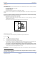
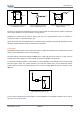
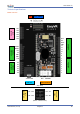
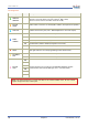
Pin assignment
Group
Pin
Description
●
ARDUINO
HEADERS
-
Arduino UNO-R3 Shield interface, pass-through connectors
(Pins 0-1 are in use when J12 is set to UP, PC, HW or LEO)
(Pins 12-13 or 8-9 are in use when J12 is set to SW)
●
EASYVR
AUDIO
-
Audio cables connectors of the EasyVR 3 module (microphone and speaker)
●
LINE OUT
-
3.5mm stereo/mono jack (16Ω - 32Ω headphones or line-level output)
●
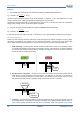
MODE
JUMPER
SW
Arduino Software Serial (connected to pins 12-13 or 8-9)
HW
Arduino Hardware Serial (connected to pins 0-1)
PC
PC Mode (Arduino disabled, EasyVR in command mode)
UP
Update Mode (Arduino disabled, EasyVR in boot mode)
LEO
Leonardo Update (Arduino enabled, EasyVR in boot mode)
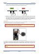
●
PROG
-
Red light indicator for Flash programming modes (UP and LEO)
●
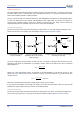
SW SERIAL
PINS
RX
Use resistor to select Software Serial RX pin: 12 or 8
TX
Use resistor to select Software Serial TX pin: 13 or 9
●
EASYVR
GPIO
IO1
General purpose I/O as found on the embedded EasyVR 3 module
(referenced at the internal VDD logic level – see note below)
IO2
IO3
IO4
IO5
IO6
Note: The General Purpose I/O lines (IO1-IO6) are at nominal 3.0VDC level. Do not connect
higher voltages directly to these pins!