
User Manual

www.veear.eu
User Manual (1.0.14) EasyVR 3 21
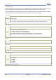
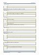
Mode Jumper settings
This jumper selects the operating mode of the EasyVR Shield and it can be placed in one of four positions:
o SW – Software Serial mode
Use it for controlling the EasyVR module from your Arduino sketch through a software serial port
(using pins 12-13). You can also connect the EasyVR Commander in this mode, provided that the
running sketch implements bridge mode (see the Arduino library examples).
o HW – Hardware Serial mode
Use it for controlling the EasyVR module from your Arduino sketch through the hardware serial
port (using pins 0-1).
o PC – PC Connection mode
Use it for direct connection with the EasyVR Commander. In this mode, the Arduino controller is
held in reset and only the embedded USB/Serial adapter is used.
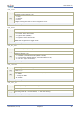
o UP – Flash Update mode
Use it for firmware updates or to download sound table data and custom grammars to the on-
board flash memory from the EasyVR Commander. In this mode, the Arduino controller is held in
reset and only the embedded USB/Serial adapter is used. The EasyVR module is set in boot mode.
o LEO – Leonardo Update mode
This is similar to the regular Flash Update mode, for Arduino boards that don’t have a separate
USB/Serial adapter, such as Arduino Leonardo. The EasyVR module is set in boot mode, but the
Arduino controller is not reset and it must be running the special “bridge” sketch.
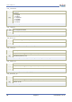
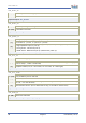
Software Serial Pins settings
On the bottom side of the board there are two SMD resistors that you can move to select the two pins of
Arduino that the EasyVR will be connected to when in Software Serial mode (Mode Jumper on SW).
o RX – Software Serial Receiver pin
D12 – Use digital pin 12 as serial receiver (default)
D8 – Use digital pin 8 as serial receiver
o TX – Software Serial Transmitter pin
D13 – Use digital pin 13 as serial transmitter (default)
D9 – Use digital pin 9 as serial transmitter
The choice of pins 12-13 is maintained for backward compatibility with the previous hardware revisions of
the EasyVR Shield. However those pins may also be used for the SPI interface, so another choice of pins 8-
9 is provided. If you want to use different pins make sure the receiver pin supports change interrupts.