
User`s manual

Connecting Power and Motors to the Controller
26 AX500 Motor Controller User’s Manual Version 1.9b. June 1, 2007
Controller Power
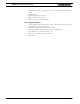
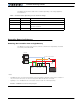
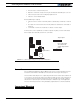
The AX500 uses a flexible power supply scheme that is best described in Figure 8. In this
diagram, it can be seen that the power for the Controller’s processor is separate from this
of the motor drivers. In typical applications, the VMot is connected in permanence to the
battery while VCon is connected to the battery through a On/Off switch.
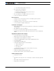
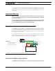
VMot
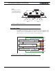
Motor 2 Motor 1
M2+ M1- M1+ VMotM2- 3 x Gnd
VCon
FIGURE 7. AX500 Controller Rear View
Note:
Both VMot terminals are
connected to each other in
the board and must be
wired to the same voltage.
Channel 1 MOSFET Power Stage
Channel 2 MOSFET Power Stage
5Vmin
30V max
Microcomputer &
MOSFET Drivers
8V min
30V max
5Vmin
30V max
Vcon
Vmot
M1-
M2-
M1+
M2+
Vmot
GND
GND
GND
FIGURE 8. Representation of the AX500’s Internal Power Circuits