
Schematic
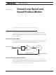
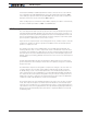
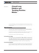

Closed Loop Speed Mode
122 Advanced Digital Motor Controller User Manual V1.8, August 28 2017
Position Counte
r
Trajectory
Speed
Command
PWM
Motor
Position Feedback
Expected
Position
-
PID
The controller incorporates a full-featured Proportional, Integral, Differential (PID) control
algorithm for quick and stable speed control.
The closed loop speed mode and all its tuning parameters may be selected individually for
each motor channel.
Motor Sensors
The controller can use a variety of sensors for measuring speed. For brushed DC, Digital
Optical Encoders and Analog Tachometerss may be used. For Brushless motors, the Hall
sensors and all other types of rotor sensors can be use in addition to Encoders and Ta-
chometers. Digital Optical Encoders may be used to capture accurate motor speed.
Analog tachometers are another technique for sensing speed. See “Connecting Tachome-
ter to Analog Inputs” on page 50
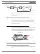
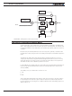
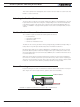
Tachometer or Encoder Mounting
Proper mounting of the speed sensor is critical for an effective and accurate speed mode oper-
ation. Figure 10-1 shows a typical motor and tachometer or encoder assembly. It is always pref-
erable to have the encoder connected to the motor shaft rather than at the output of a gearbox.
If the encoder must be mounted after a gear box consider the effect of the gear backlash. A
higher count encoder will typically be required to compensate for the lower rotation speed.
Position Sensor
Gear box
Position Feedback
Speed feedback
Analog Tachometer
or Optical Encoder
FIGURE 10-1. Motor and speed sensor assembly needed for Close Loop Speed mode
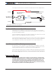
Tachometer wiring
The tachometer must be wired so that it creates a voltage at the controller’s analog input
that is proportional to rotation speed: 0V at full reverse, +5V at full forward, and 0 when
stopped.