
Schematic
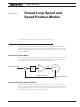
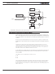

Closed Loop Speed Mode
124 Advanced Digital Motor Controller User Manual V1.8, August 28 2017
Determining the right polarity is best done experimentally using the Roborun utility (see
“Using the Roborun Configuration Utility” on page 349) and following these steps:
1. Configure the controller in Open Loop Mode using the PC utility. This will cause the
motor to run in Open Loop for now.
2. Configure the sensor you plan to use as speed feedback. If an analog tachometer
is used, map the analog channel on which it is connected as “Feedback” for the se-
lected motor channel. If an encoder is used, configure the encoder channel with the
encoder’s Pulses Per Revolution value. On brushless motor, if the rotor sensor (Hall,
Sin/Cos, ..) sensors are used, configure the correct number of motor pole pairs.
3. Click on the Run tab of the PC utility. Configure the Chart recorder to display the
speed information if an encoder is used. Display Feedback if an analog sensor is
used.
4. Verify that the motor sliders are in the “0” (Stop) position.
5. If a tachometer is used, verify that the reported feedback value read is 0 when the
motors are stopped. If not, adjust the Analog Center parameter.
6. Move the cursor of the desired motor to the right so that the motor starts rotating,
and verify that a positive speed is reported. Move the cursor to the left and verify that
a negative speed is reported.
7. If the reported speed polarity is the same as the applied command, the wiring is cor-
rect.
8. If the tachometer polarity is opposite of the command. If an encoder is used, swap
its ChA and ChB outputs. Alternatively, swap the motor leads if using a brushed DC
motor only. The speed polarity can also be inverted by entering a negative number
of encoder PPR. On brushless motors, entering a negative number of poles will also
invert the speed measured by the Hall, SinCos, or SPI sensor.
9. Set the controller operating mode to Closed Loop Speed mode using the Roborun
utility.
10. Move the cursor and verify that speed stabilizes at the desired value. If speed is un-
stable, tune the PID values.
Important Warning
It is critically important that the tachometer or encoder wiring be extremely robust.
If the speed sensor reports an erroneous speed or no speed at all, the controller will
consider that the motor has not reached the desired speed value and will gradually
increase the applied power to the motor until the closed loop error is triggered and
the motor is then stopped.
Controlling Speed in Closed Loop
When using encoder feedback or Hall Sensor (brushless motor) feedback, the controller
will measure and report speed as the motor’s actual RPM value.
When using analog or pulse as input command, the command value will range from 0 to
+1000 and 0 to -1000. In order for the max command to cause the motor to reach the de-