
Schematic

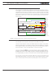


Controller Powering Schemes
Advanced Digital Motor Controller User Manual 27
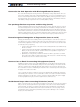
Connection for Safe Operation with Discharged Batteries (note 1)
The controller will stop functioning when the main battery voltage drops below 7V. To en-
sure motor operation with weak or discharged batteries, connect a second battery to the
Power Control wire/terminal via the SW1 switch. This battery will only power the control-
ler’s internal logic. The motors will continue to be powered by the main battery while the
main battery voltage is higher than the secondary battery voltage.
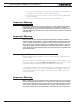
Use precharge Resistor to prevent switch arcing (note 2)
Insert a 1K, 0.5W resistor across the SW2 Emergency Switch. This will cause the control-
ler’s internal capacitors to slowly charge and maintain the full battery voltage by the time
the SW2 switch is turned on and thus eliminate damaging arcing to take place inside the
switch. Make sure that the controller is turned Off with the Power Control wire grounded
while the SW2 switch is off. The controller’s capacitors will not charge if the Power Control
wire is left floating and arcing will then occur when the Emergency switch is turned on.
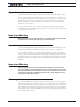
Protection against Damage due to Regeneration (notes 3 and 4)
Voltage generated by motors rotating while not powered by the controller can cause seri-
ous damage even if the controller is Off or disconnected. This protection is highly recom-
mended in any application where high motion inertia exists or when motors can be made
to rotate by towing or pushing.
• Use the main SW1 switch on the Power Control wire/terminal to turn Off and keep
Off the controller.
• Insert a high-current diode (Digikey P/N 10A01CT-ND) to ensure a return path to the
battery in case the fuse is blown. Smaller diodes are acceptable as long as their
single pulse current rating is > 20 Amp.
• Optionally use a Single Pole, Dual Throw switch for SW2 to ground the controller
power input when OFF. If a SPDT switch cannot be used, then consider extending
the diode across the fuse and the switch SW2.
Connect Case to Earth if connecting AC equipment (note 5)
If building a system which uses rechargeable batteries, it must be assumed that periodi-
cally a user will connect an AC battery charger to the system. Being connected to the AC
main, the charger may accidentally bring AC high voltage to the system’s chassis and to
the controller’s enclosure. Similar danger exists when the controller is powered via a pow-
er supply connected to the mains.
Some controller models in metallic enclosures are supplied with an Earth tab, which per-
mits earthing the metal case. Connect this tab to a wire connected to the Earth while the
charger is plugged in the AC main, or if the controller is powered by an AC power supply
or is being repaired using any other AC equipment (PC, Voltmeter etc.)
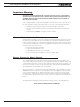
Avoid Ground loops when connecting I/O devices (note 6)
When connecting a PC, encoder, switch or actuators on the I/O connector, be very careful
that you do not create a path from the ground pins on the I/O connector and the battery
minus terminal. Should the controller’s main Ground wires (thick black) or terminals be
disconnected while the VMot wires (thick red) or terminals are connected, high current
would flow from the ground pins, potentially causing serious damage to the controller
and/or your external devices.