
Schematic
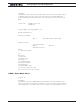

Analog, Digital, Pulse IO Configurations
Advanced Digital Motor Controller User Manual 303
1: Motor on
2: Motor reversed
3: Overvoltage
4: Overtemperature
5: Mirror status LED
6: No MOSFET failure
Example:
^DOA 1 3 : Output 1 is active when Overvoltage is observed
Note:
Typical default configuration is Digital outputs 1 (2) are active when motor is on. Digital
output 2 (3) when no MOSFET failure is detected.
To activate an output via serial command or from a Microbasic script, set that output to
Never
DOL - Digital Outputs Active Level
HexCode: 12
Description:
This parameter configures whether an output should be set to ON or to OFF when it is
activated.
Syntax Serial: ^DOL cc aa
~DOL
Syntax Scripting: setconfig(_DOL, cc, aa)
Number of Arguments: 1
Argument 1: ActiveLevels
Type: Unsigned 32-bit
Min: 0 Max: 2 ^ Total Number of Digital
Outputs
Default: 0 = All active high
Where:
cc = Digital input number
aa=
0: On when active
1: Off when active
PCTR - Pulse Center Range
HexCode: 20