
Schematic

Connecting a Voltage Source to Analog Inputs
Advanced Digital Motor Controller User Manual 47
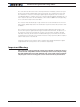
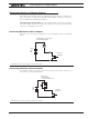
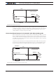
A pull up resistor must be installed when using a pull down switch.
33kOhm
5V Out
20kOhm
1K to
10
K
Ohm
Ground
DIN
FIGURE 3-5. Pull down (Active Low) switch wirings to DIN pins
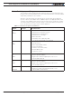
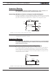
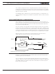
Connecting a Voltage Source to Analog Inputs
Connecting sensors with variable voltage output to the controller is simply done by mak-
ing a direct connection to the controller’s analog inputs. When measuring absolute voltag-
es, configure the input in “Absolute Mode” using the PC Utility.
0-5V
Source
Internal Resistors
and Converter
+5V
Ground
AIN
A/D
20kOhm
33kOhm
V
FIGURE 3-6. 0-5V Voltage source connected to Analog inputs
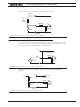
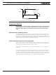
Using external resistors, it is possible to alter the input voltage range to 0V/10V or
-10V/+10V.
33kOhm
20kOhm
Internal Resistors
and Converter
+5V
Ground
A/D
4.7kOhm
0-1
0V
4.7kOhm
Figure 3-7. External resistor circuit for 0 to 10V capture range