
Schematic
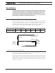
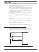

Connecting Sensors and Actuators to Input/Outputs
52 Advanced Digital Motor Controller User Manual V1.8, August 28, 2017
0
0.5
1
1.5
2
2.5
3
3.5
4
4.5
- 40
- 30
- 20
- 10
0
10
20
30
40
50
60
70
80
90
100
110
120
130
140
150
Volts
oC
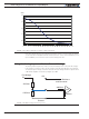
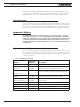
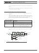
FIGURE 3-13. Voltage reading by Controller vs NTC temperature
Note: The voltage values in this chart are provided for reference only and may vary based
on the Thermistor model/brand and the resistor precision. It is recommended that you ver-
ify and calibrate your circuit if it is to be used for safety protection.
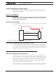
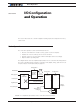
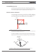
Using the Analog Inputs to Monitor External Voltages
The analog inputs may also be used to monitor the battery level or any other DC voltage.
If the voltage to measure is up to 5V, the voltage can be brought directly to the input pin.
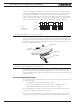
To measure higher voltage, insert two resistors wired as voltage divider. The figure shows
a 10x divider capable of measuring voltages up to 50V.
47kOhm
IN
Ext Voltage
4.7kOhm
Internal Resistors
and Converter
A/D
33kOhm
20kOhm
+5V
Ground
FIGURE 3-14. Battery Voltage monitoring circuit