
Schematic


Connecting Multiple Magnetic Guide Sensor
Advanced Digital Motor Controller User Manual 69
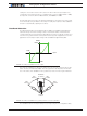
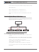
The following Motor Controller queries are available for reading the captured sensor data.
?MGD : Read tape detect
?MGT nn : Read left track when nn= 1 or right track when nn= 2
?MGM nn : Read left marker when nn=1 or right track when nn= 2
Details on these commands can be found in the Commands Reference section of this
manual
Connecting Multiple Magnetic Guide Sensor
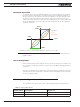
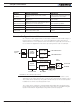
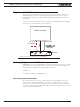
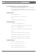
More than one sensor can be connected to a single motor controller. This can be useful
in AGV designs that must be able to move in the forward and reverse direction along the
guide. Connecting multiple sensor can be done by connecting each sensor to one of the
available pulse input, as shown in the figure below.
GND
Pulse In 1
Pulse In 2
Pulse In n
7-30V Supply
Motor Controller
Figure 5-2: Connecting multiple sensors to a motor controller
Accessing Multiple Sensor Information Sequentially
Two methods are available for accessing each sensor’s data when multiple sensors are
connected.
The first method is to only have one sensor enabled at any one time. This is done by en-
abling and disabling pulse inputs via serial commands or MicroBasic scripting. Examples:
^PMOD 1 0 : Serial command to Disable Sensor on pulse input 1
Setconfig(_PMOD, 1, 0) : Microbasic instruction to disable sensor on Pulse input 1
^PMOD 2 4 : Enable Sensor on Pulse input 2
Setconfig(_PMOD, 2, 4) : Microbasic instruction to enable sensor on Pulse input 2
The sensor information can then be accessed with the ?MGD, ?MGT and ?MGM function
discussed above.