
Schematic


Brushless Motor Connections and Operation
74 Advanced Digital Motor Controller User Manual V1.8, August 28 2017
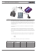
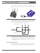
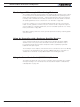
FIGURE 6-1. Controller’s possible command modes
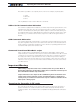
In the Serial mode, the mode is considered as active if commands (starting with “!”)
arrive within the watchdog timeout period via the RS232 or USB ports. The mode will
be considered inactive, and the next lower priority level will be selected as soon as the
watchdog timer expires. Note that disabling the watchdog will cause the serial mode to be
always active after the first command is received, and the controller will never switch to a
lower priority mode.
In the pulse mode, the mode is considered active if a valid pulse train is found and re-
mains present.
In analog mode, the mode is considered active at all time, unless the Center at Start
safety is enabled. In this case, the Analog mode will activate only after the joystick has
been centered. The Keep within Min/Max safety mode will also cause the analog mode to
become inactive, and thus enable the next lower priority mode, if the input is outside of a
safe range.
The example in Figure 6-1 shows the controller connected to a microcomputer, a RC ra-
dio, and an analog joystick. If the priority registers are set as in the configuration below:
1- Serial
2- Pulse
3- Analog
then the active command at any given time is given in the table below.
TABLE 6-1. Priority resolution example
Microcomputer
Sending commands
Valid Pulses
Received
Analog joystick
within safe Min/Max Command mode selected
Ye s Don’t care Don’t care Serial
No Ye s Don’t care RC mode
No No Ye s Analog mode
No No No User selectable default value
Set
R
eset
Serial/USB
Pulse
Analog