
Schematic

Trapezoidal Switching
Advanced Digital Motor Controller User Manual 93
Trapezoidal Switching
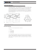
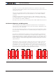
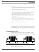
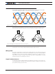
In trapezoidal switching, the controller applies current to two of the 3 motor wires, in turn
and in alternating direction. A total of 6 combination of current flow are possible, resulting
in the rotor getting a changing magnetic field every 30 degrees of electrical rotation. The
controller must therefore know where the rotor is in relation to the electromagnets so
that current can be applied to the correct winding at any given point in time. The simplest
and most reliable method is to use three Hall sensors inside the motor. The diagram be-
low shows the direction of the current in each of the motor’s windings depending on the
state of the 3 hall sensors.
Figure 8-2. Hall sensors sequence
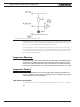
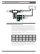
Hall Sensor Wiring
Hall sensors connection requires 5 wires on the motor:
• Ground
• Sensor1 Output
• Sensor2 Output
• Sensor3 Output
• + power supply
Sensor outputs are generally Open Collector, meaning that they require a pull up resistor
in order to create the logic level 1. Pull up resistor of 4.7K ohm to +5V are incorporated
inside all controllers. Additionally, 1nF capacitors to ground are present at the controller’s
input in order to remove high frequency spikes which may be induced by the switching at
the motor wires.