
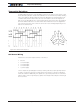
Schematic
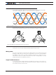

Brushless Motor Connections and Operation
96 Advanced Digital Motor Controller User Manual V1.8, August 28, 2017
Motor
U
V
W
Vw-u
Probe
Probe
Rotate
shaft
clockwise
GND Clip
GND Clip
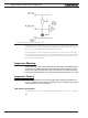
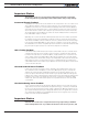
Hall Sensor Power and Pull-ups
HA
Va
+5V
2-10k
2-10k
2-10k
HB
HC
GND
5V
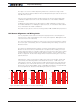
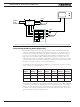
Figure 8-5. Use an oscilloscope and the circuit in figure to place the probes and generate these signals
Determining the Wiring Order Empirically
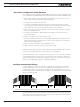
While probing with an oscilloscope gives the definite order, a simpler and quicker way
may be to try all valid combination by trial and error. To do this, you can either connect
the motor wires permanently and then try different combination of Hall sensor wiring, or
you can connect the Hall sensors permanently and try different combinations of motor
wiring. There is a total of 6 possible combinations of wiring three sensors on three con-
troller inputs. There are also 6 possible combinations of wiring three motor wires on three
controller outputs. Only one of the 6 combinations will work correctly and smoothly while
allowing the controller to drive the motor in both directions.
The table below show the 6 possible combinations of connecting motor wires 1, 2 and 3
to the controller’s U, V and W outputs.
Controller
Output
Motor
Wiring 1
Motor
Wiring 2
Motor
Wiring 3
Motor
Wiring 4
Motor
Wiring 5
Motor
Wiring 6
U 1 1 2 2 3 3
V 2 3 1 3 1 2
W 3 2 3 1 2 1
Try the different combinations while applying a low amount of power (5 to 10%). Applying
too high power may trigger the stall protection. Be careful not to have the motor output
wires touch each other and create a short circuit. Once a combination that make the mo-
tor spin is found, increase the power level and verify that rotation is smooth, at very slow
speed and at high speed and in both directions.